DSO138 oscilloscope
This is review of DSO138 oscilloscope clone and small project involving interfacing it with PC (device library for miniscope v4).
DSO138 DIY kit for this project was sponsored and provided by

DSO138 is an inexpensive low-speed miniature oscilloscope with 2.4" LCD display, based on STM32F103 MCU. It was developed by JYE Tech, but apparently it is cloned and distributed also by few other manufacturers. In this case - 56dz.com.
Package contains PCB, display, remaining components, cable with BNC connector and two crodile clips and 4-page instruction with schematic. External power supply (9V typ.) is required.
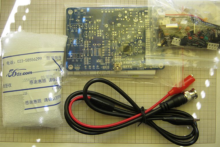
STM32 and mini-USB are already soldered.
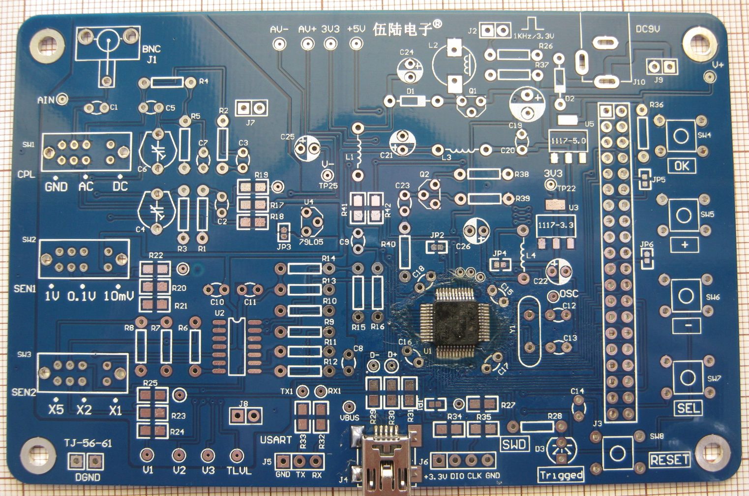
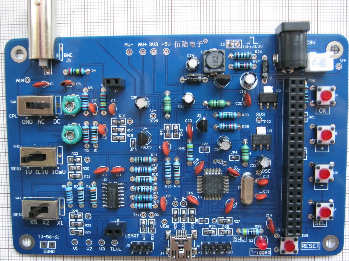
Components are a mix of THT and SMD (0805 resistors). Most resistors are from 1% tolerance group.
I was little surprised with 100nF capacitors - their real capacitance as measured was ~35nF. It is not critical, but
I guess some extra 0805 100nF can be soldered on the bottom side.
Supplied manual is in Chinese only. Assembling is rather obvious and JYE Tech documents can be also used as reference, but
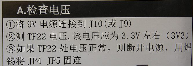
there is one important difference - in JYE Tech instruction JP5 and JP6 jumpers should be open, but for my unit this
resulted in white screen (= display initialization error). As far as I can translate this manual fragment - JP5 should be short here.
This "white screen" problem was pretty tricky as it was intermitting - with JP5 open from time to time display was correctly initialized,
but often was giving graphical artifacts and was going back to white after time.
Same as with JYE Tech - JP3 and JP4 must be closed (after testing if +5V and +3.3V supply is correct).
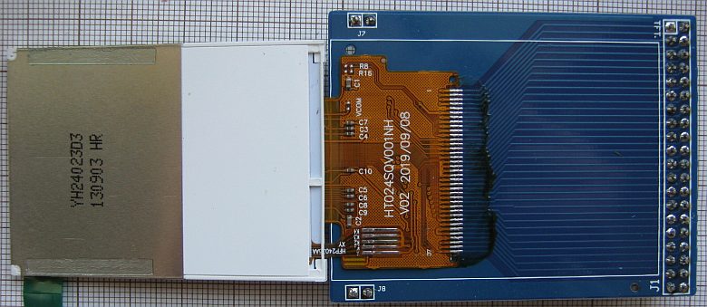
PCB has quite a few testing points, half of them accessible even when display is attached.
Display is held on separate PCB with two strips of double sided tape. I was double checking tape soldering as possible cause of "white screen" issue before finding out this was just JP5 not being closed.
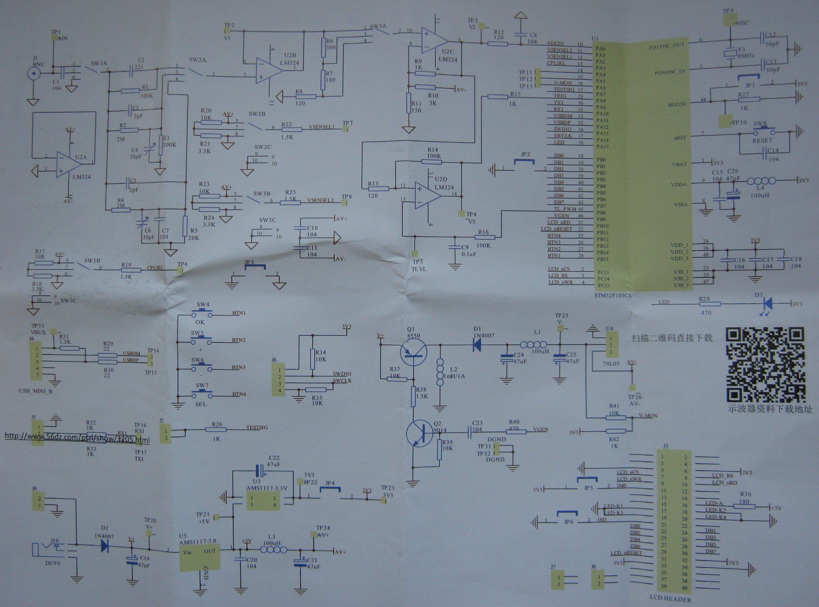
One weird difference between JYE Tech and 56dz.com versions is anti-aliasing filter (R12, C8). I don't see any other elements limiting bandwidth (except from opamp limitations). R12 is 120Ohm in both versions, but on JYE Tech schematic C8 is 120pF and on 56dz.com: 100nF. Neither value seems "correct" (relatable to 1MHz sampling rate) - for 120pF we are getting cutoff/-3dB at 11MHz and for 100nF at 13.3kHz. I would recommend using something in range from 3.3nF to 10nF instead (~400kHz...132kHz).
It's quite likely that component selection for this type of kit is semi-random (whatever is available/cheapest at the moment) and "Trigger" LED on my kit was way too bright - I've swapped R28 from 470Ohm to 3300Ohm.
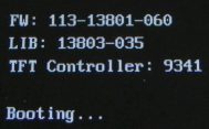
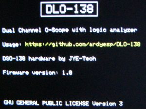
"Booting" screen is displayed for about 2 seconds, giving hint about overall firmware structure with two
separate version numbers for "main application" (113-13801-060) and "library" (13803-035).
On JYE Tech there is source code described as "initial", version 113-13801-037.
I've prepared EmBitz project (easier to rebuild with single, 50MB IDE + compiler, simple install that just works, easy debugging) with this source: DSO138_EmBitz.zip.
Most of functionality comes as libdso138.a pre-compiled binary
library. There is documentation for this library (12040_582.pdf), although it is closed source and not
too useful. There were two DSO138 versions with different gain in analog part and this library is not matching actual hardware,
giving ~3x too high voltage readouts. Fortunately there is another, independent firmware project - DLO-138.
Just in case you want to go back to initial firmware, here is dump: original_firmware.bin.
If you have any other hardware version I would strongly recommend backing up original firmware before trying any alternative.

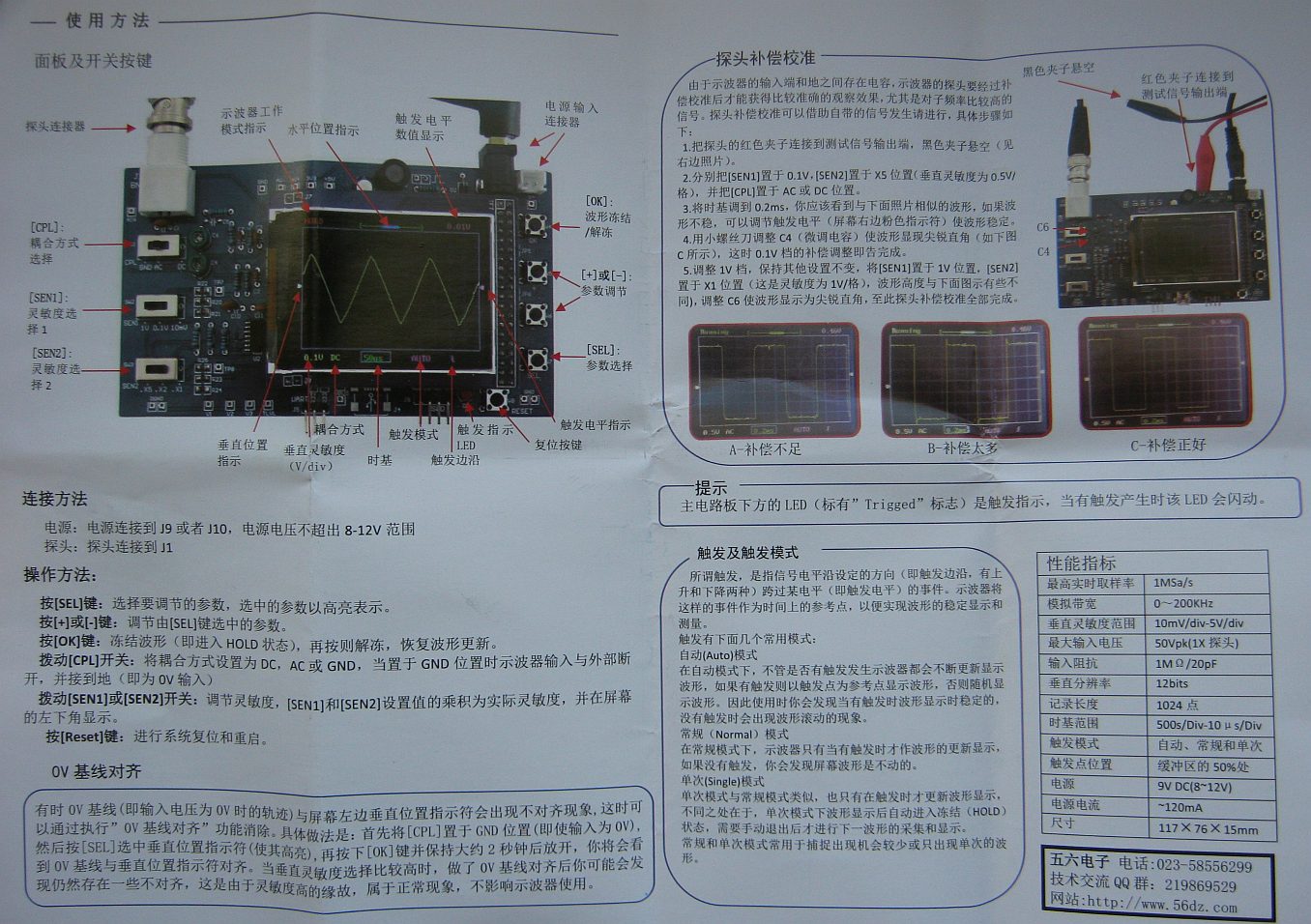
Manual pages: 1, 2, 3 and schematic.
For updating firmware I've used STLink clone. Using UART bootloader is another option, but it was less convenient when experimenting as it requires detaching display board, closing jumper, re-attaching display and rebooting cycle. For one-time update update either method would be fine.
DLO-138 firmwware changes user interface a little and is adding second analog channel and two digital channels.
I've used compiled DLO-138 firmware file from github, DLO-138_switches_1.0.bin - with ever changing arduino environment and libraries compiling it is not straightforward.
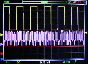
Additional channels can be disabled. Settings are kept after restart (EEPROM emulation in FLASH).
DLO138 firmware is using SWD pins as "logic analyzer"/digital input channels. I don't like this setup (SWD debugging would not work, but I guess it was no option with arduino anyway), but updating firmware still works if RESET button is used. Note that digital channel #1 (SWDIO) has 3.3V pull-up and digital channel #2 (SWCLK) has pull-down, both with 10k resistors.
One more addition that comes with DLO138 firmware is data output over serial port. Data is pushed when HOLD is used ([OK] button during normal operation) as text, at 115200bps, 8N1. Transmission of complete data packet takes about 3 seconds. Packet contains data from all the channels, even disabled (hidden) ones. There are 2048 lines with tab-separated data. Example:
Net sampling time (us): 40944
Per Sample (us): 19.99
Timebase: 0.5 mS/div
Actual Timebase (us): 499.80
CH1 Coupling: DC, Range: 2V/div
CH2 Coupling: --, Range: +-2048
Triggered: YES
CH1 Stats (V):
	Vmax: 4.98, Vmin: 1.42, Vavr: 3.21, Vpp: 3.56, Vrms: 3.64
	Freq: 1000.39, Cycle: 1.00 ms, PW: 0.50 ms, Duty: 50.00 %

Time	CH1	CH2	D_CH1	D_CH2
0.00	4.90	146	1	0
19.99	4.88	151	1	0
39.98	4.90	180	1	0
59.98	4.90	181	1	0
79.97	4.90	177	1	0
99.96	4.92	150	1	0
119.95	4.90	149	1	0
139.95	4.90	44	1	0
159.94	4.90	43	1	0
179.93	4.88	42	1	0
...
20472.00	1.55	43	1	0	<--TRIG
20491.99	1.57	43	1	0
20511.98	1.57	42	1	0
20531.98	1.57	195	1	0
20551.97	1.57	195	1	0
...
(total of 2048 data lines)
Channel 1 data contains voltage, channel 2 - raw ADC value (12 bit signed).
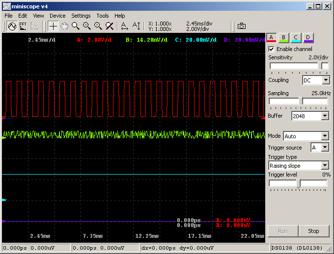
DSO138/DLO138 + miniscope v4
I've prepared simple interface dll for miniscope v4 allowing to show DLO138 output on PC screen. DLO138 is outputting text over serial port (example above) when HOLD function is used ([OK] button is pressed). This is only single direction communication, device cannot be controlled from PC - this also means that connecting GND and UART TX pin to PC is sufficient.
Miniscope v4 was updated to version 4.01.01, adding few callbacks for controlling GUI from device - setting proper position of sampling frequency trackbar, sensitivity trackbar and coupling type combobox when new frame was received.
Note: only voltage for first channel is correct/synchronized with the device. Second analog channel would capture only noise unless some wire would be soldered to PA4 / TP11 (test point near the chip, without description).
Miniscope v4 + dso138.dll binaries: dso138_miniscope.zip.
Source code for dso138.dll: dso138_dll_src_20200415.zip.
Thanks to digitspace for providing kit.