Miniscope v2c
Very cheap low-speed dual channel PC/USB oscilloscope with STM32 (STM32F103C8T6) microcontroller.
- follows miniscope v2b idea, using miniscope v4 application as PC GUI,
- using very cheap STM32F103 MCU in LQFP48 package ($4),
- single-sided PCB suitable for homemade prototyping using toner transfer method,
- sampling: 2x461 kSps (2x300 kSps with older firmware), 8 bit, real-time data streaming to PC (USB full-speed),
- UART bootloader (less convenient that USB SAM-BA from Atmel),
- single sensitivity range, 0...6.6V and non-standard 20 kOhm input impedance (unfortunately with larger resistances channel crosstalk and ADC input current leak effects are visible - some R2R opamp would be good addition; note: resistance can be increased when using newer firmware that is using independent ADCs for channel A and channel B).
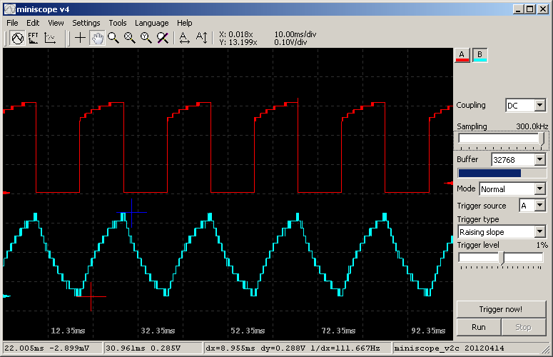
Some low amplitude signals (300 mV p-p) recorded with miniscope v4:
Components should cost less than $10 total (with homemade PCB).
Schematic: miniscope_v2c_20120416.pdf
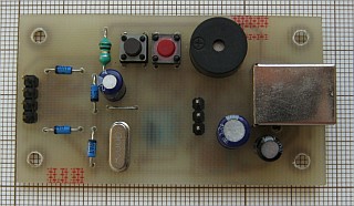
Single-sided Eagle PCB, 66mm x 36mm
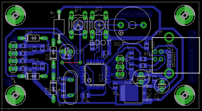
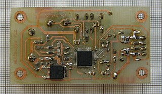
Goldpin header and BOOT pushbutton are used to load firmware via UART.
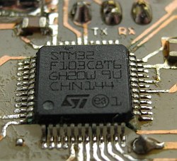
STM32F103C8T6: LQFP48 package
IDE
CDC class example - same path as with miniscope v2 - from STM was selected as a base project to speed-up USB device related programming. This example has project files for IAR, Keil, RIDE, HiTOP and TrueSTUDIO, so using one of these IDEs would be an advantage. Unfortunately I haven't found any of these appropriate. RIDE and HiTOP evaluation versions have restrictive licenses (valid support contract requirement after 7 days and no commercial usage respectively). IAR or Keil evaluation/lite version licenses have restrictions on output size and it wouldn't be a problem in a small project, but they have pretty big disk space requirements (~3 GB as I recall) and their installers don't allow much customization. Same goes with TrueSTUDIO.
As a result I've chosen CooCox toolchain - 115 MB download for IDE + gcc, ~800 MB disk space usage after installation, no license restrictions.
Firmware loading
PCB has no JTAG/SWD connector so firmware has to be uploaded with UART bootloader. To enter bootloader mode press and hold BOOT pushbutton while pressing RESET pushbutton. PC loader (STM "Flash Loader Demo") seems to work with no problems with USB-UART converter. MCU bootloader pins are 5V tolerant, so either 3.3V or 5V RS232-UART/USB-UART converter can be used.
RESET pushbutton can be removed - microcontroller will go into bootloader mode also if it would be powered on (USB would be connected) when BOOT is held down.
Since there is no USB 1k5 pull-up control USB need to be re-plugged to force re-enumeration after reset of new firmware loading.
Some basic project to test MCU and buzzer: stm32scopeTest.7z.
Tips on USB transfer speed
Use CDC example as a template. There are two BULK endpoints. For better transfer speed CDC example would require small modifications.
- Change VCOMPORT_IN_FRAME_INTERVAL to lower value. I'm not sure if value = 1 is suitable when transfer needs to be bidirectional, so I've used value = 2. It won't make much difference though.
- Increase USART_RX_DATA_SIZE. I've used 8192 bytes (2 x 4 kB), but I think that there would be no speed difference with values above 4096 B (maximum number of data would be transmitted in every or almost every frame).
- Modify Handle_USBAsynchXfer so it wouldn't transmit data unless half of the USART_Rx_Buffer would be full. Thus after each SOF maximum number of bytes would be sent. If there is a chance that buffer would be filled with low speed or not filled at all for some time then some kind of timeout would be needed here that would cause transmitting whatever is in buffer already - you may know this problem if you've used USB to UART converters before.
On a PC side make sure that application is constantly ready to accept new data. Make sure that thread that is reading data is working with higher priority than others. I've used libusb, so I've used combination of usb_submit_async/usb_reap_async to enqueue multiple read requests, each time requesting reading of 4096 B. I guess with WinUSB that could be made with overlapped I/O. Miniscope v2b/v2c dll interface library passes than data through FIFO to GUI application.
I wasn't interested in high PC to device speed, so I haven't any tips on reverse direction. Miniscope v2c (very similar to v2b) is streaming data to PC at maximum speed all the time. Transfers in reverse direction are insignificant (ID request, changing analog gain or analog coupling).
Firmware and miniscope v4 dll interface
- 2012.04.16 Initial release, NOT RECOMMENDED:
stm32scope_20120416.7z
miniscope_v2c_dll_20120416.7z - 2012.04.21 Lots of fixes to both dll and firmware:
stm32scope_20120421.7z
miniscope_v2c_dll_20120421.7z- FIXED: framing error in dll code causing trace discontinuity when recording and displaying multiple continuous data buffers,
- few fixes and improvements related to USB TX queue (i.e. more optimal memory allocation between ADC buffer and USB TX FIFO) in firmware and RX queue in dll,
- extended buffer sizes list to 128 kB.
- 2012.04.28 miniscope_v2c_dll_20120428.7z
- FIXED: if trigger was in continuous mode but stopped (Run/Stop) single manual trigger caused working as if Run was pressed.
- 2012.04.29 Putting available hardware to better use - using both ADCs in simultaneous
mode allowed to increase sampling speed from 2x300 to 2x461 kSps and increasing
S/H time to 13.5 cycles at the same time. Although ADCs can still work faster increasing
speed further would not allow to keep real-time USB full-speed streaming to PC which is
essential feature making it possible to use large sample buffer sizes and record signal
continuously.
stm32scope_20120429.7z
miniscope_v2c_dll_20120429.7z -
2012.06.07 FIXED: no buzzer sound at startup (delay loops removed at o3 optimization).
stm32scope_20120607.7z -
2012.10.06 Thanks to Openmoko assigning USB PIDs to open
source projects miniscope v2c has got it's own unique
VID = 0x1d50, PID = 0x604f pair.
stm32scope_20121006.7z
miniscope_v2c_dll_20121006.7z -
2012.12.16 Added device library built with Code::Blocks/MinGW,
stm32scope_cb.7z as a reference project.
Tested only for a moment, previous (Turbo C++ project) library version should
be preferred in general.
2020.07.15 Updated Code::Blocks/MinGW project source: stm32scope_cb_20200714.7z. As newest Code::Blocks 20 comes with 64-bit MinGW and is missing 32-bit Windows libraries - use Code::Blocks 16. -
2013.09.16 Updated device library, miniscope_v2c_dll_20130916.7z:
- FIXED: occasional data loss (with log: "RX FIFO overflow") observed when thread was suspended by OS for larger times than requested; strangely this was behavior was observed with no consistency, with light system load and when debugger/IDE was not running,
- extended samples buffer sizes list up to 1MS (x 2 channels).
-
2017.01.21 Updated device library, miniscope_v2c_dll_20170121.zip,
DLL is now partially configurable without recompiling as sensitivity ranges can be changed using JSON file created in dll directory (miniscope_v2c_capabilities.cfg).
This is default file content, that defines single gain range (25.78 mV/bit or 6.6V/256 per bit):
{
   "Capabilities" : {
      "Coupling" : [ 1 ],
      "Sensitivity" : [ 0.02577999979257584 ]
   },
   "Other" : {
      "bitsPerSample" : 9,
      "signalInverted" : false,
      "signalOffset" : 0
   }
}
File below adds two additional sensitivity ranges (50 mV/bit and 100 mV/bit - without firmware support it relies only on some manual switch), accepts inverted signal with "0" in the middle (inverting amplifier that shifts voltage so oscilloscope can measure positive and negative voltages), using value = 127 - value formula for samples received from device. There is also AC coupling added (just for reference, not making much sense without support in firmware actually).{ "Capabilities" : { "Coupling" : [ 1, 2 ], "Sensitivity" : [ 0.02577999979257584, 0.05000000074505806, 0.1000000014901161 ] }, "Other" : { "bitsPerSample" : 8, "signalInverted" : true, "signalOffset" : 127 } }Using JSON editor is recommended as invalid JSON content would be overwritten by DLL.
Note: floating point numbers with lots of not-so-significant digits are actually effect of reading and writing back by JSON library in DLL with lack of proper rounding.
Note 2: in this setup "bitsPerSample" reported to GUI is changed to 8 bits, that is real number of ADC bits used. 9 bits in default setup just give better default zoom when oscilloscope is able to measure only positive voltages. This also sets correct range for trigger level.
In this version slope trigger was also changed to simpler one, with less filtering. While previous version might be more stable in time it was also prone to not firing with some signals, in particular slowly changing. - 2019.08.10 Firmware as EmBitz project: stm32scope_embitz_20190810.zip
- 2019.08.11 Firmware + dll set with base sampling frequency lowered to 292kSps (this seems to eliminate FIFO/USB overflow problems resulting in lack of data continuity): stm32scope_embitz_20190811.zip, miniscope_v2c_dll_20190811.zip.
Although windows driver (libusb-win32) is included in dll archive using Zadig is actually easier and
it is only sensible option for 64-bit Win8/Win10:
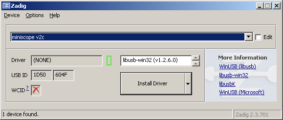
Important: make sure libusb-win32 is selected as driver in Zadig (WinUSB might be default).
Update from 2024.07.04: when installing on Win7 x64, Zadig 2.9 (current version) failed - Device Manager was showing that driver is not digitally signed.
Going back to Zadig 2.5 (like on the picture above) solved this issue.
Follow-ups
PCB version with LM1117 3.3V regulator and few layout changes made with Pulsonix EDA software by Quang Duy: http://mritx.blogspot.com/2014/07/low-speed-dual-channel-pcusb.html.
Alternative hardware
Apparently ebay (and most likely any other shopping site of your choice) is flooded with very cheap ($5 including shipping)
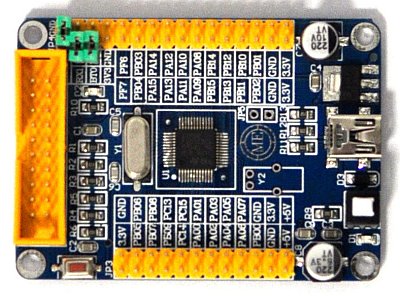
Maple-like minimalistic STM32F103C8T6 boards. While I haven't tested them they seem like good choice to run this firmware.
Don't forget that USB-UART (or RS232-UART if you have RS232 in your PC) converter is required to load program to microcontroller.
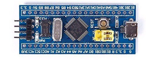
STM32F103C8T6 board
