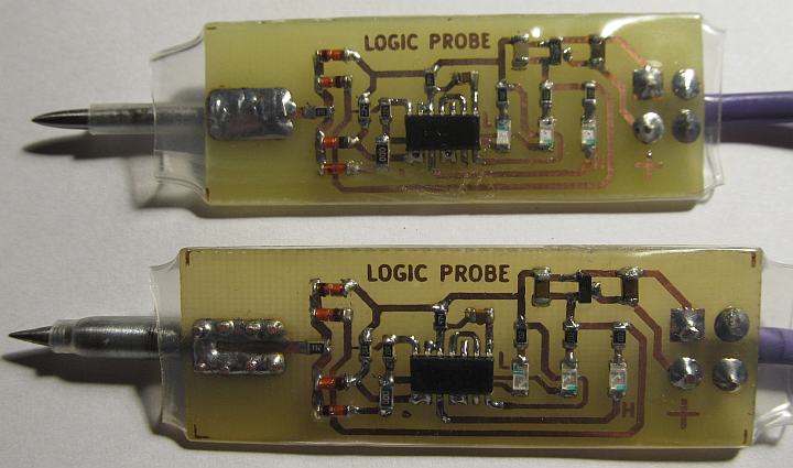
Logic probe
I usually have logic analyzer and at least one low speed digital oscilloscope at hand, but simple logic probe is still invaluable for initial troubleshooting. My previous logic probe was built based on "7400 na 10 sposobów", article series with mini projects based on 7400 published in Polish "Elektronika Praktyczna" magazine in summer of 1995.
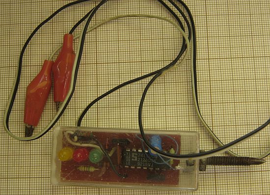
It is able to distinguish high impedance (no LED active), high/low digital states (red/green LEDs) and also signal short pulses (yellow LED, pulse length entended by univibrator).
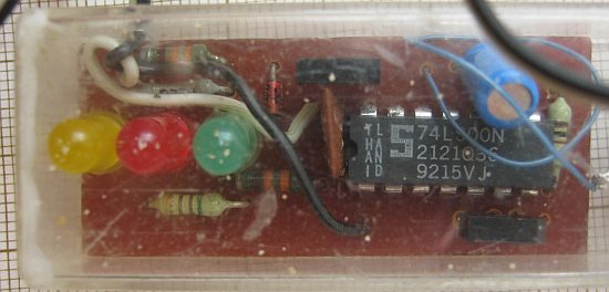
This is still very useful tool, although my build is not too esthetic, there is some wear and corrosion and most importantly this probe requires 5V power supply which is more and more rare these days (typically probe is powered from tested board), so it was time for update.
Circuit from "Elektronika Praktyczna" would not work correctly with more modern CMOS-based gates. After looking for similar DIY probes I've tried
this kind first:
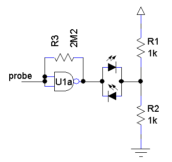
In my test this kind of probe was giving misleading readings though - if input was attached to some capacity (e.g. 1 meter of wire not connected
anywhere else) both "H" and "L" LEDs were activated. Possible false reading with high impedance source was a deal breaker.
So, I've built something closer to my previous probe, but using more modern CMOS gates and able to operate with 3.3V power supply.
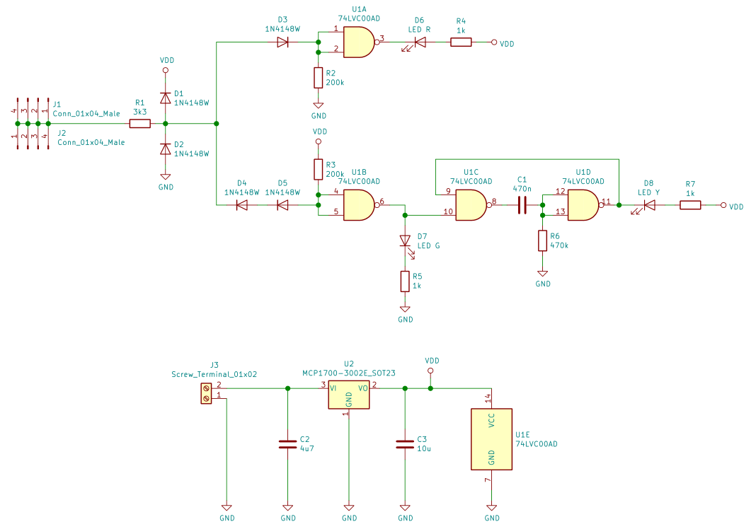
Notes:
- replacing either D4 or D5 diode with jumper or 0 Ohm resistor might be recommended; while both diodes seemed to be needed with initial testing with 3.3V supply and HC-series gates, for my final setup with 3V supply (MCP1700 3V regulator) and LVC gates single diode works better, giving "H" state for voltages over 1.74V and "L" state for voltages under 0.72V
- types and values of most components are not critical - other CMOS NAND like 74HC00 would work also (might be slower though), small signal diodes I've used were actually scavenged from old motherboards, same as 1206 capacitors near the voltage regulator
- voltage regulator (3V MCP1700) actually requires only single 1u capacitor at output - most likely any "big" capacitors from old motherboard or graphics card would work (0805 can be soldered as well as 1206)
- used voltage regulator is rated for up to 6V input voltage (power supply)
- some experimenting with LED resistors might be needed; diodes I've used come from 5x20 1206 LED pack from aliexpress and green one seems to be more bright than yellow and red - for me this was not a problem
- watch out for LED polarity when assembling - for green one cathode is connected with serial resistor, for two others - anode; 1206 LEDs I've bought have symbol printed on bottom side
- J1 and J2 connectors are used as pads for needle mounting
Schematic: logic_probe.pdf.
Kicad 5 files: logic_probe_kicad.zip.
Bottom copper printout (for thermotransfer): logic_probe-B.Cu.pdf.
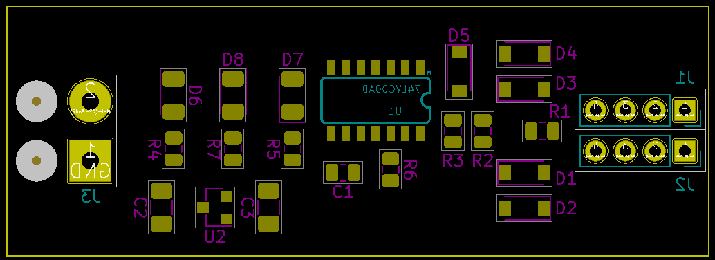
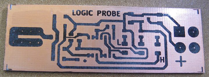
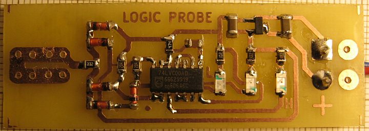
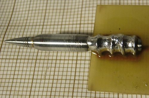
Metal tip was made from some PCB standoff on improvised lathe (drill machine + file). It is held by four soldered wire (~1.0 mm diameter) loops.
Extra pads on the other side of PCB are intended to hold ground/supply cable with soldered loop.

Layer of transparent acrylic spray adds durability to PCB.

Transparent shrink tube is used as inexpensive housing.
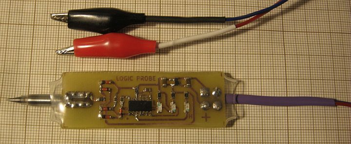

As described, one of the diodes was replaced with 0 Ohm resistor. Having all the components and multiple copper layer printout already I've made
second piece to keep one at home and one at workplace.
