Simple BFO metal detector
Base Frequency Oscillator (BFO) detector is the simple type of metal detector, based on the principle of comparing output frequency of test generator (with relatively large coil sweeping in the search area) with the output frequency of reference generator. This type of detector is not used anymore in professional constructions and this device didn't meet my expectations in terms of detection range (in practice: ~20 cm in air for 0.8 kg transformer) and stability placing itself in a toy class category. Basically, it has no strong points beside simplicity, low cost and low current consumption.
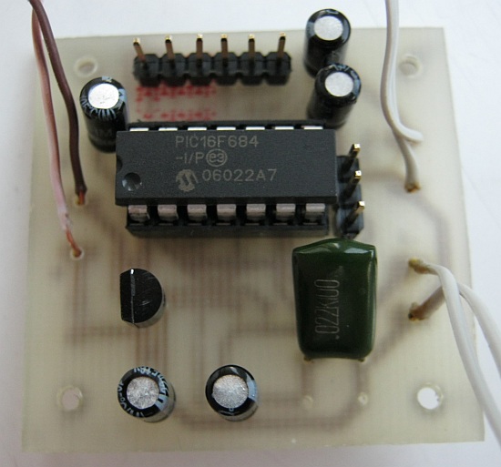
Device is using PIC16F684 - inexpensive ($1.50 at local distributor) 8-bit microcontroller with 2k x 14bit of FLASH memory, 128B of RAM, ISP interface, 2 analog comparators, 3 timers (including one 16-bit), internal RC clock source and few other common features like POR and BOD, all in 14-pin package. It is classified as part of mid-range family by the manufacturer, although that can be misleading when comparing with e.g. low-end ARM chips. On the plus side (apart that I already had it lying in my drawer) it has wider supply voltage range (2.0 - 5.5 V) and plenty of EEPROM (256B, 2 times more than RAM!).
Search generator is based on PIC16F684 built-in analog comparator - it's very common schematic and you may find similar in e.g. microntroller LC meters. Output signal of the generator is feeded back to timer 1 clock input (Schmitt gate input) that is counting pulses for a specified period of time. This period of time (250ms set in firmware) is measured with PIC internal oscillator (working as reference oscillator). Timer 1 (only one 16-bit timer) clock input is shared with XTAL input, so more stable crystal oscillator could not be used. Fortunately internal oscillator long time / temperature / voltage drift and miscalibration can be ignored because of adopted automatic calibration operation - absolute frequency of test and reference generators is not important, device is responding only to short term frequency changes comparing current frequency with average frequency from previous 20 measurements.
When difference between current frequency and average frequency is detected, one of two tones is generated, depending on relation between these numbers. Different tones are used for coarse metal discrimination - moving coil near ferromagnetic material results in lower tone than sweeping it over non-ferromagnetic one (e.g. coins or solder spool). Not so known fact (or omitted in many publications) is that oscillator frequency can fall also in presence of ferromagnetic object due to eddy currents effects (same effects that allow non-ferromagnetic objects detection). Some non-uniformly shaped object can change oscillator frequency in both directions depending on angle between them and coil.
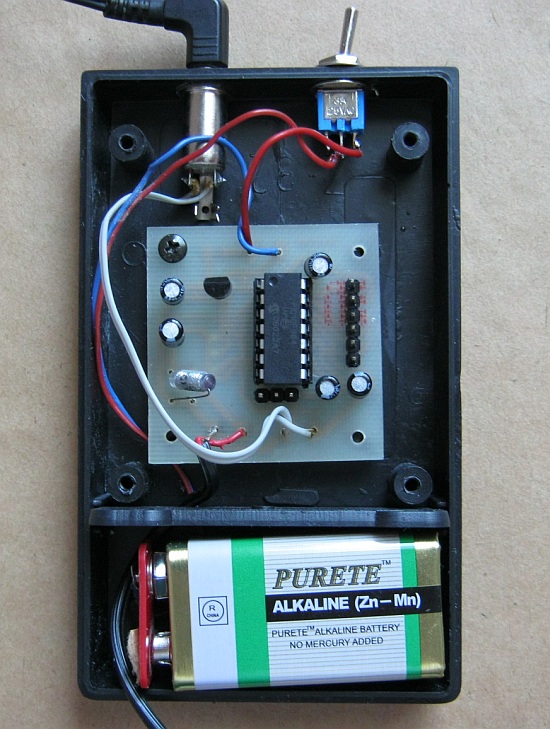
Detector is powered with 6F22 (9V) battery. Significant portion of current consumption is caused by voltage regulator (78L05 consumes few mA), you can replace it with similar low quiescent current regulator in same package to double battery life. Still, regular zinc-carbon 6F22 battery has 400 mAh capacity (alcaline: 560 mAh) which would result in over 100 hours work time (measured current: 3.9 (idle) - 4.1 (audio sound) mA).
Hardware
Schematic: metal_detector.pdf
Eagle 6.4 files: mdet.zip.
Remarks:
- search generator frequency can be changed with C5, C6 capacitors (doubled to make searching for exact value easier)
- audio volume and amplitude of harmonics (sound is more or less similar to one generated by 8-bit computers) can be changed with R6, C7
PCB: 41 mm x 41 mm, single sided, relatively low precision requirements are making it suitable for toner transfer etching.
Used case: Z-32 (black plastic, 110 mm x 65 mm x 26 mm, with 6F22 battery compartment, $1.50 at local distributor).
Search coil details
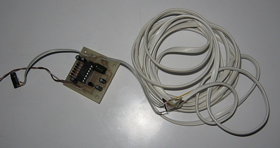
In initial tests ad-hoc coil - ~12 turns of 4-wire phone cable connected together giving ~48 turns on ~10 cm diameter was used.
With 22 nF capacitor generator frequency was around 100 kHz. In general lower frequency (~50 kHz) is more desirable due to smaller losses and thus higher detection
range in soil. Be aware that if generated signal is > 256 kHz counter would overflow and frequency readings may look strange.
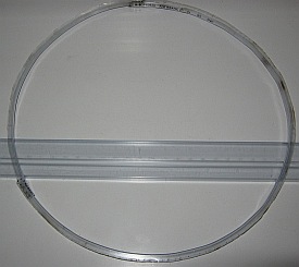
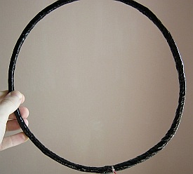
My actual search coil was made out of cut, bent and clued together plastic (antistatic) tubes that were used for LM317 voltage regulator.
With 25 cm diameter, 75 turns of 0.4 mm enameled wire and 2n2 cap in parallel resonant frequency was around 50 kHz.
Wiring on C-shaped frame was protected with cheap PET tape, shielded with aluminum foil connected to ground (note: shield must not be closed)
and protected with two crossed layers of PVC insulating tape.
Apart from mechanical stability most important characteristic of search coil is its diameter. Increasing diameter increases detection range but decreases sensitivity for small objects - my test ad-hoc coil was more sensitive to small objects like coins than my second coil. Interesting thing is that object dimensions are more important than mass - detection range for aluminum clue tube is similar to detection range for power transformer.
Measured later coil parameters with TC-1 tester: 3.82 mH, 23.1 Ohm.
Another idea for search coil I heard of is using thin aluminum or copper pipe as coil mechanical support and electric shield in one. After forming circle from tube (do not forget to leave slit, circle can not be closed) cut thin slit longways with hacksaw to be able to wind coil inside the pipe. Make sure that coil is working fine (you won't be able to go back), than wrap pipe around with insulation tape to cover the slit and fill it with two component epoxy or another resin.
Firmware
Firmware was built with microC compiler/IDE. It's relatively lightweight tool (~30MB download, ~140MB installed) and limitations
of free demo version are not significant in this application, so I preferred it over MplabX + XC8 set from Microchip.
MetalDetectorFW.zip
For debugging purposes (since microC IDE does not support PICkit2 directly) software UART (TX part used only) is available on PCB. It may be useful for checking test generator frequency when using with untested search coil.
I've uploaded copy of used microC IDE as https://github.com/tomek-o/microC_PRO_PIC. I've tried also to use SDCC, but unfortunately it generates roughly twice as large code. It is a big limitation as program size is too large after enabling UART debugging in this case.