Miniscope v2e
Extremely cheap low-speed PC/USB oscilloscope with STM32 (STM32F042) microcontroller.
Quick specification
- follows miniscope v2a-d idea: very simple device streaming data in real time to PC; DLL and GUI (Win32) are handling all the functionality,
- sampling: 480 kSps, 8 bit, single voltage range, streaming via USB FS with libusb (32/64bit) used as driver,
- record length: 4k to 1M defined in DLL; up to 512M samples when recording to file,
- firmware loading via USB (DFU bootloader embedded in ROM),
- low component count: MCU, voltage regulator, mini-USB and few passive SMD components on single-sided PCB.
Announced in January 2014 Cortex-M0 microcontroller family that features crystal-less USB FS device allows to cut noticeable part of BOM when building oscilloscope/recorder similar to miniscope v2c/v2d. STM32F042F devices are interesting in particular because of small and friendly TSSOP20 package with minimum number or power lines.
STM32F042F4 devices feature USB bootloader (DFU), single 1MSps ADC (so single channel sampling would be preferred to avoid crosstalk issues), 16 kB FLASH memory (~2 times more than needed) and 6 kB RAM.
Schematic
miniscope_v2e_20140501.pdf
1k5 USB pull-up should not be mounted as STM32F042 has internal pull-up - apparently used by ROM DFU bootloader also.
Version from 2015.02.20 is intended to use R8 27k and R4 51k for input divider.
Either 3V (that is one I've actually used) or 3.3V voltage regulator can be used.
Comparing this schematic with Discovery kit for STM32F072 indicates that few other passive components (RC at USB D+/D-)
may be redundant.
If you do not plan to experiment with firmware heavily (or don't mind some hanging wires at the time) you can
replace SMD microswitch with some sort of jumper as it is needed only for firmware upgrading.
Eagle files
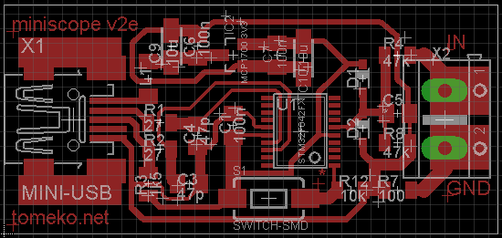
Early, mixed THT/SMD, not optimized board: miniscope_v2e_eagle.zip
STM32F042Fx Eagle library: STM32F042Fx.lbr
Current version: miniscope_v2e_eagle_20150113.zip.
SMD only. Intended to be wrapped in transparent heat-shrink tube with needle probe soldered to input.
Panelized PCB printout for toner transfer method: miniscope_v2e_pcb_panelized.pdf
Interesting fact: only STM32F042, 100nF capacitors (buying few hundreds is cheap and they won't waste) and MCP1700 (thanks to Microchip for
their sample program, but they are also quite reasonably priced - $0.35 ea from local retailer) are new parts in this unit, all others are reused - mini USB
and microswitch come from mp3 player and all else (SMD choke, 10u electrolytic capacitors, Schottky diodes, two 0805 47pF capacitors and 0805 resistors) from old CD-ROM. Disclaimer: no working or worth fixing device suffered.
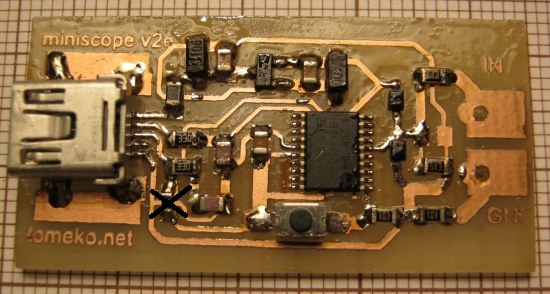
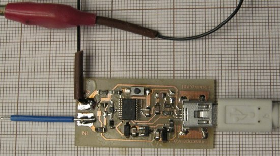
With soldered needle probe (paperclip), mini alligator clip as GND connector and mini-USB cable:
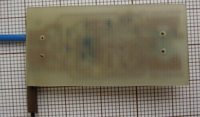
Top: (almost) no drilling:
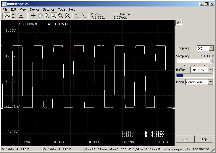
PC application (miniscope v4), capturing PWM signal driving TDA7052A volume control in my TEA5767 radio:
From practical testing - for this probe type form thin USB cable without ferrite EMI filter at mini-USB side
would be recommended for convenience. Plastic SD card box may serve as a case, although it is
almost twice as large as my PCB.
Firmware
Initial release (for reference only, use updated version!).
ADC configuration used: 8bit resolution (9.5 cycles for SAR), 13.5 cycles sampling time, 12MHz ADC clock.
Resulting sampling speed = 12M/(13.5+9.5) = 521.7k [Sps].
Note: DLL is configured for 6V range (my board is actually using 3V voltage regulator). For 6.6V range (when using 3.3V voltage
regulator and 1:2 divider) either rebuild DLL or use miniscope v4 calibration feature - 10% difference is allowed as calibration
setting.
Firmware (Keil v5 Lite): miniscope_v2e_20150215.7z
DLL (TC++ Explorer) + win driver: miniscope_v2e_dll_20150215.7z
2015.02.20 update
- fixed bug in USB FIFO
- voltage range changed to 0...8.6V: 51k+27k resistors; this minimizes problem with unexpected microcontroler ADC input leakage
- reduced sampling frequency to 480kSps; in testing with higher sampling occasional frame drop was spotted and this is not acceptable as continuous sampling and recording (real time, gapless USB streaming) is key feature of this device
Starting up
Miniscope v2e is very similar to v2d as both STM32F0x2 and STM32F3 use USB DFU bootloader embedded in ROM.
To enter bootloader mode detach power supply/interface (USB), press microswitch and while holding it attach USB again. You should see new device notification and DFU device would appear in device manager. Use STM DFUse demo or equivalent application to upload miniscope_v2e.dfu image to device. Right after upload finishes new device would appear.
Miniscope v2e firmware is based on CDC example and so far I was too lazy to modify USB descriptors and debug it afterwards, thus it enumerates as composite device. Interface 01 is the one that handles bulk transfers and appropriate driver (libusb) is included in DLL archive. Once driver is installed device would appear under libusb-win32 group in device manager. Interface 00 (remains of CDC control interface) is unused and will be left without driver.
Same as with miniscope v2c or v2d main application is a separate download - miniscope v4. After extracting it copy miniscope_v2e.dll into /device subdirectory. Start miniscope v4 and select this DLL at startup dialog.
Issues
- ADC input of STM32F0 in continuous behaves behaves like weak voltage source: there is low voltage (~220mV) present on oscillocope input even if it
is disconnected; I'm hoping for possible explanation and/or workaround from STM forum.
Firmware from 2015.02.20 assumes that input divider has 51k+27k resistors, giving 8.6V measurement range at 3V supply. With this divider described problem is neglectable - input offset is equal to ~3 ADC units.