RDA5807M (+ arduino nano clone) FM radio
Simple FM radio receiver based on RDA5807M and AVR microcontroller with IR controller. Cheap arduino nano clone is used - it's actually cheaper than mega8 from local distributor (taking shipping cost into account), it provides convenient way of programming (bootloader), debugging (integrated USB-to-serial CH340 bridge) and can also provide 3.3V voltage required by RDA5807M.
Cheap ($0.99 for 2 pieces) RDA5807M are available on ebay and aliexpress. Depending on register address used for communication, RDA5807M can be used as compatible with
TEA5767 or in "native" mode. I've tested TEA5767 mode first and having some problems with station seeking switched to "native" mode.
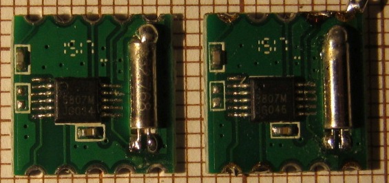
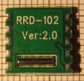
RDA5807M vs TEA5767:
- (+) RDS (I'm not interested in it at the moment though)
- (+) volume control (15 steps) - useful as it allows using amplifier with no own volume control (for previous TEA5767 radio I was using TDA7052A - amplifier with voltage-controlled gain, driven by AVR PWM, but it limits choice)
- (+) integrated amplifier capable of driving headphones directly
- (+) probably better reception/sensitivity (as most people claim - it's difficult to verify but I also think RDA5807M is better)
- (-) supply/interface voltage limited to 3.3V
- (-) poor documentation (more on this later)
Main issue with arduino is in my opinion licensing - as arduino libraries are covered by LGPL their commecial use is problematic - using it might just be not worth the trouble. As my ATmega8 version of this radio was built with avr-gcc/WinAVR there was also no compelling reason for switching to arduino ecosystem - all the missing parts (NEC IR decoding code) are also available in pure C as well (and with BSD-like licensing).
Few notes on arduino / AVR bootloader
Arduino nano clone I bought (popular <$2 board with mini-USB socket) had bootloader already programmed.
ATmega328P has special Flash area designated for bootloaders - located at the end of the Flash area. Flash programming can be initiated only if code is running from this area. Size of the bootloader area is determined by two fuse bits: BOOTSZ1 and BOOTSZ0 - can be set to either 256 words (512B or 4 Flash pages), 512 words, 1024 words or 2048 words (4kB). Entering the bootloader could be done either from application (jump) or by programming BOOTRST fuse (setting value = 0) that would change reset vector from application (0x0000) to bootloader making bootloader running by default. This is what arduino is using. Including code that jumps to bootloader in user application would result in problems as user application might just hung, disable interrupts or serial port. Instead each time programming is requested PC application sets DTR line low for a short time. This line is connected with AVR RESET input with 100nF capacitor and since BOOTRST fuse is programmed microcontroller starts executing bootloader code on reset. Bootloader waits few seconds for communication, jumps to application on timeout. As same PC application is controlling DTR state and initiates communication bootloader timeout can be short and all works smoothly. Note that while bootloader is very convenient it adds few seconds to cold startup (i.e. when turning power on) which might be annoying.
As user application Flash area starts from 0x0000 regardless whether bootloader is used or not no changes to the application are required if working with or without bootloader. Application can be developed with help of the bootloader but does not depend on it.
Here is arduino configuration (excerpt from boards.txt) for arduino nano:
nano.name=Arduino Nano

nano.upload.tool=avrdude
nano.upload.protocol=arduino

nano.bootloader.tool=avrdude
nano.bootloader.unlock_bits=0x3F
nano.bootloader.lock_bits=0x0F

nano.build.f_cpu=16000000L
nano.build.board=AVR_NANO
nano.build.core=arduino
nano.build.variant=eightanaloginputs

## Arduino Nano w/ ATmega328
nano.menu.cpu.atmega328=ATmega328
nano.menu.cpu.atmega328.upload.maximum_size=30720
nano.menu.cpu.atmega328.upload.maximum_data_size=2048
nano.menu.cpu.atmega328.upload.speed=57600
nano.menu.cpu.atmega328.bootloader.low_fuses=0xFF
nano.menu.cpu.atmega328.bootloader.high_fuses=0xDA
nano.menu.cpu.atmega328.bootloader.extended_fuses=0x05
nano.menu.cpu.atmega328.bootloader.file=atmega/ATmegaBOOT_168_atmega328.hex
nano.menu.cpu.atmega328.build.mcu=atmega328p
This bootloader (atmega/ATmegaBOOT) is GPL-licensed. Optiboot has same license yet arduino FAQ mentions only LGPL licensing. In bird culture, this is considered a dick move.
For firmware loading arduino is using avrdude version 6.0.1. As WinAVR is not maintained anymore and contains version 5.10 from 2010 you might need to update these files. Avrdude command line for writing Flash (replace COM16 with own port number):
avrdude -p atmega328p -c arduino -P COM16 -b 57600 -D -U flash:w:main.hex:i
These parameters are also included in project makefile (make program).
Arduino bootloader is not able to read fuses (returning 0) but fuses can be verified from avr-gcc application itself:
static void dump_fuses(void)
{
	uint8_t lfuse, hfuse, efuse, lock;

	cli();
	lfuse = boot_lock_fuse_bits_get(GET_LOW_FUSE_BITS);
	hfuse = boot_lock_fuse_bits_get(GET_HIGH_FUSE_BITS);
	efuse = boot_lock_fuse_bits_get(GET_EXTENDED_FUSE_BITS);
	lock = boot_lock_fuse_bits_get(GET_LOCK_BITS);
	sei();
	printf("LFUSE = %02X, HFUSE = %02X, EFUSE = %02X, LOCK = %02X\n", lfuse, hfuse, efuse, lock);
}
Fuses on my board are little weird (LFUSE = FF, HFUSE = DA, EFUSE = F8, LOCK = CF) as BOD level in EFUSE was programmed to restricted value.
IR kit
Main addition to previous (ATmega8) version is infrared remote control. For this purpose I've bought cheapest "arduino" IR kit: tiny remote controller, VS1838B IR receiver and (unnecessary) board for this receiver. Remote controller seems to be really low quality - it was only $1.27 including shipping and I'm not even sure if it is worth it, so only plus is it is easily replaceable and manufactured in millions. Mine is almost unused, just laying around few months but front is already delaminated.
Controller is intented to be powered with CR2025 cell but popular and cheap CR2032 fits also.
I've accidentally discovered that this kit can work with depleted cell (2.90V with no load, 1.25V on 1k load) but range is limited to ~30 cm then.
With fresh cell this remote + receiver set works across the room (few meters) with no problems, although it requires aiming.
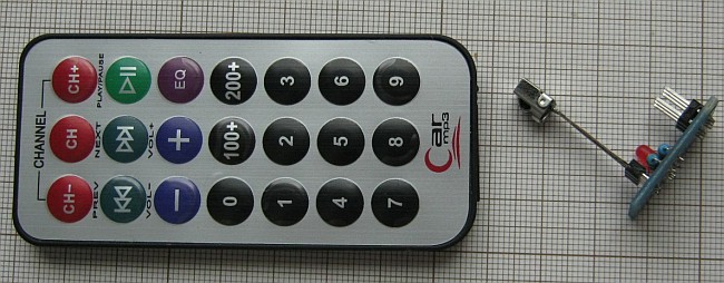
This remote sends signals following NEC protocol (basic variant with 8 bit address)
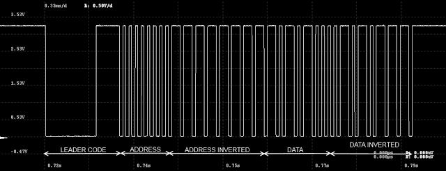
For precise time readings: NEC.json for miniscope v4
For decoding NEC protocol I've used slightly modified nec-decoder library by Malte Pöggel. Timings generated by my $1 remote were little different than nominal (e.g. 10 ms burst) and original code was not accepting this.
NEC standard codes sent by remote have address = 0x00 and following command values (hexadecimal):
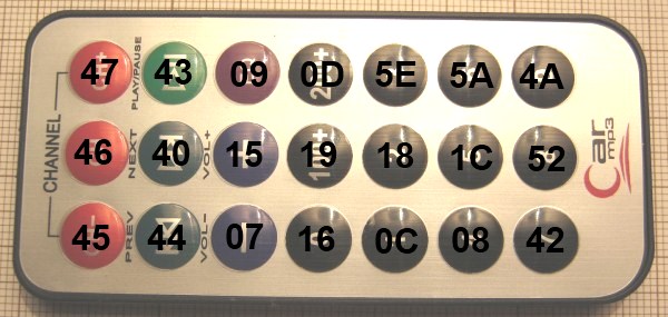
I've received very similar remote controller with popular USB DVB-T RTL2832U tuner:
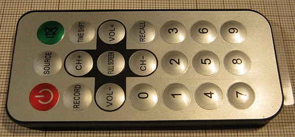
It has identical size to "Car mp3" controller, NEC address code is identical (0x00) but command codes assigned to buttons are different.
You can change mapping from NEC command code to function (ON/OFF, VOLUME UP/DOWN, SEEK UP/DOWN, ...) in ir_remote_s1_car_mp3.c file.
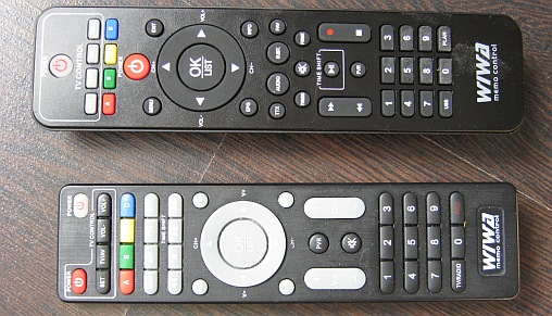
Another popular remote controllers that are using NEC codes are ones from DVB-T tuners based on MSTAR chip:
PAM8403
PAM8403 is a D-class stereo audio amplifier running from 5V power supply. For $1.50 I've received 3 modules:

RDA5807M documentation
Poor documentation might be main issue of RDA5807M. There are two datasheet version on the Internet, 1.0 and 1.1, both from 2011 and they are (surprisingly) written in close to correct English, but it seems that either chip was updated or documentation was incomplete and this cost me few solid hours. In "TEA5767 mode" chip had decent reception, but once I switched to native mode it was practically unusable, barely receiving any stations through the noise when placed near the window. Comparing initialization procedure with few other project initially gave no clues. Then small arduino test code got interesting as reception was good with it. Upon closer inspection that code works because it actually doesn't do anything - it sets software reset bit in R2 and apparently this causes all changes to base configuration to be ignored. With try and error R5 writing was proven to cause problem and this is register that also controls volume, so skipping writing to it was not a good option. Reading this register to get default value does not seem to be possible. Accidentally I've looked into python on RPi code - there is 0x0080 bit set in R5 (in datasheet described as "Resvered" with default value = 0) and this works. This bit deserves to be named "R5_UNDOCUMENTED_SHIT" in source code below.
As I've ordered and received my RDA5807M modules in 2018 and this undocumented bit is not set in most existing projects, my theory is that RDA5807M received some update while related datasheet version is still not available.
Schematic and Kicad files
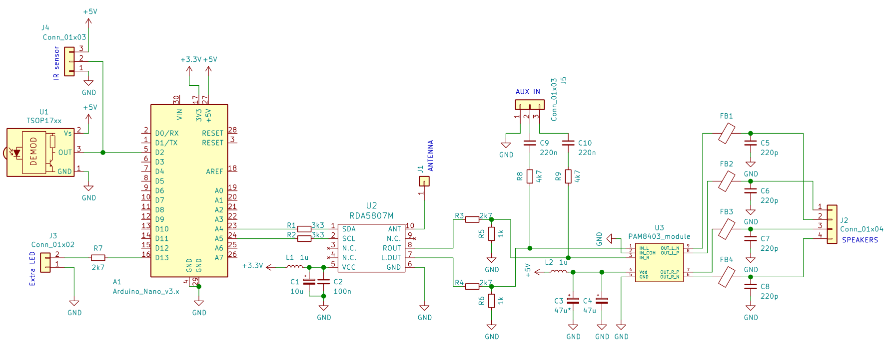
Schematic - pdf
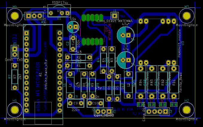
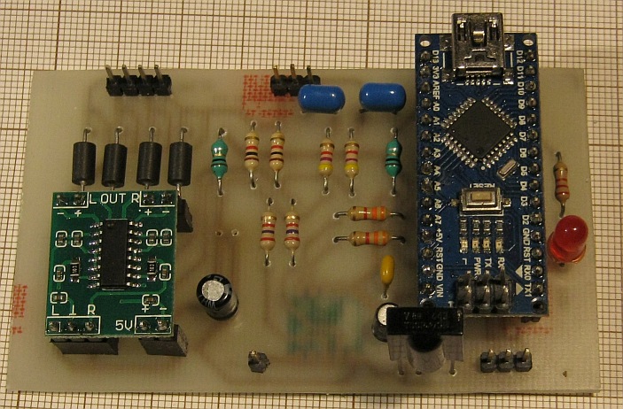
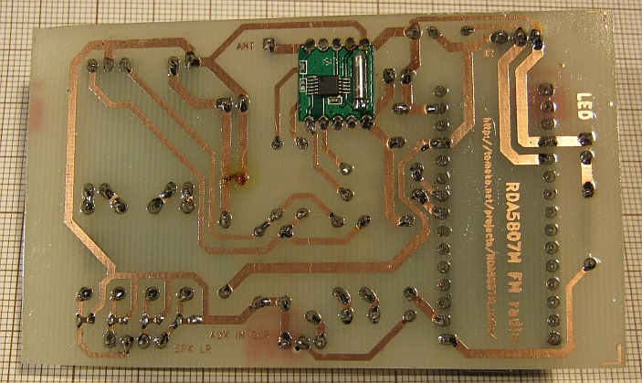
mega328_FM_Kicad.zip
Notes:
- radio is powered from mini-USB port on arduino nano clone module and is not very picky - small USB charger/power supply, PC USB port or small powerbank work fine; in my setup I'm using currently "parasite" power with 5V/1A power supply shared by always on "web thermometer" and this radio
- maximum audio volume is rather moderate, this is intended to be "kitchen"/small room audio device, full theoretical 2x3W from PAM8403 would be overkill and I care more about minimal audio volume (there are 15 volume levels from RDA5807M and lowest level is intended to be used at night time)
- J4 is alternative to soldering TSOP17xx directly - if you need to mount IR sensor to front panel
- AUX IN is - you guessed - auxiliary audio input; in my case it is connected to PC audio output thus radio works also as PC speakers
- audio signal from FM module and AUX IN is mixed together
- there is no volume control for AUX IN signal (volume control is only "inside" RDA5807M); depending on your preferences you might change R8 and R9 to lower values as with 4k7 used PC volume might need to be set to rather high values and it might be not comfortable when switching to e.g. internal laptop speakers
- device is "always on" (this also means that AUX IN always works), consuming about 50mA (or 250mW)
- there is place for two electrolytic capacitors near PAM8403 module; I've soldered only one of them to limit inrush current which might be a problem if powering from PC USB port (I believe chargers or similar power supplies do not care)
- I've used toner transfer when making PCB and I had to use "Print as image" option, otherwise some pads were missing from printout - this might be some compatibility issue with PDF generator / PDF reader / particular postscript printer
Case
I've finally used plain, cheap Z-34B enclosure with few cut outs for connectors (speaker goldpin header, mini-jack for LINE IN, IR sensor, front LED and antenna).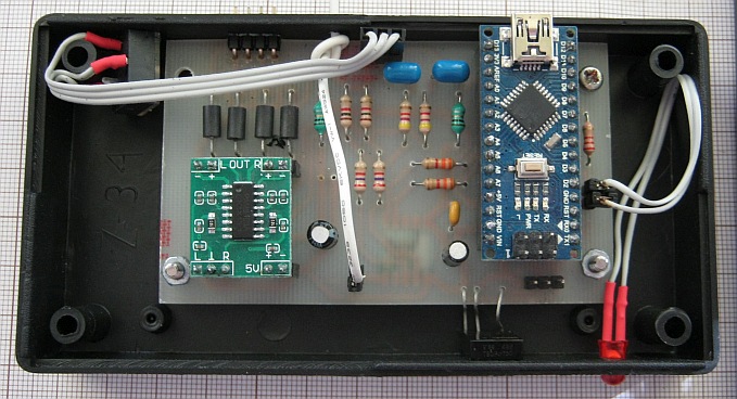
These flat speakers are salvaged from scrapped LCD TVs (LG, e.g. 42LB5610, part numberss EAB62972101, EAB62972102). Their nominal power is 5W (sometimes 10W), these bass-reflex enclosures are relatively big for TV speakers and I guess they are good match for small FM radio.

Firmware
Built with WinAVR-20100110 (latest version).
- mega328_FM_20190223.zip - initial release
- settings stored in internal EEPROM (like in my TEA5767 project)
- remote IR control, mapped buttons of $1 "Car mp3" ebay miniature remote controller working with NEC standard
- PLAY/PAUSE button = on/off
- PREV/NEXT buttons = seek down/up
- VOLUME +/-: 15 levels
- EQ = force mono
- as on/off state is stored in configuration, radio can be used without remote controller if station does not need to be changed (just by switching on/off power supply)
- plenty of debug logging through UART/USB (baudrate = 115200, 8N1), more can be enabled with "LOCAL_DEBUG" macros in C files
- mega328_FM_20190515.zip
- added station memory (10 stations switched with buttons 0...10 or with CH-/CH+)
- station programming sequence: CH button, 0...9 button, CH button
- added sleep timer function: while ON: [200+] button + 1...9 button sets sleep timer to 5...45 minutes
- added function for muting advertisements: [Play/Pause] button (to set radio to OFF state) + [200+] button + 1...9 button mutes radio for 1...9 minutes