CH341A tool
This is a Windows tool adding extra functionality to popular EEPROM/FLASH programmer based on CH341A USB to I2C/SPI/UART converter - using it as a general purpose interface.
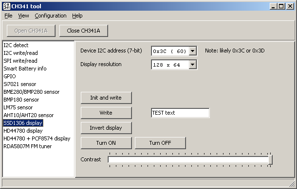

Before using this type of CH341A-based programmer check if your variant is using 5 V for CH341A power supply. There are some variants that don't have this issue or might even be able to switch between 5 V and 3.3 V (more useful / commonly used), but the ones with CH341A powered from 5 V might be still common. Example "voltage fix".
As a backup I've also got myself other board variant. It has switchable supply voltage and more pins exposed and clearly labeled.
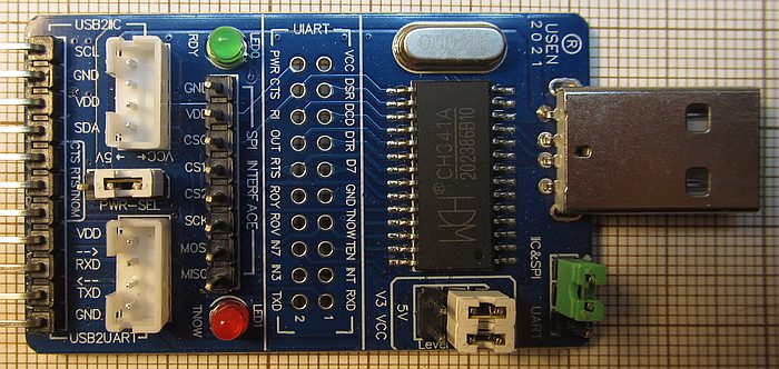
I don't consider it better in general, if you work with serial memories then first version might still be preferred.
Functions:
- detecting I2C devices
- writing/reading raw I2C data
- writing/reading raw SPI data
- writing/reading CH341A GPIO
- reading Smart Battery information
- reading data from some I2C sensors:
- BME280/BMP280
- BMP180
- Si7021
- LM75
- AHT10/AHT20
- AS5600
- VL53L0X laser ToF distance sensor
- APDS-9960 light/proximity/gesture sensor
- L3G4200D gyro
- BMI160 IMU
- MPU6050 IMU
- HMC5883L magnetometer
- VEML7700 ambient light sensor
- reading from Sensirion SHT11 sensor - using SDA/SCL pins but with its own protocol
- writing to SSD1306-based OLED display
- writing text text to HD44780 display (GPIO mode)
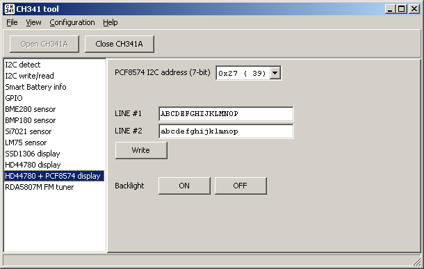
- writing text text to HD44780 + PCF8574 display (I2C)
- writing to SPI MAX7219 8x8 LED matrix
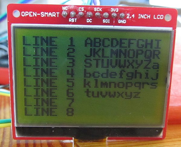
- writing to ST7567 SPI LCD
- writing to CH1115 0.5" OLED display
- controlling RDA5807M FM radio module
- controlling TEA5767 FM radio module
- controlling Si4713 FM transmitter
- controlling Si5351A clock generator
- writing to MCP4725 DAC
- working as MDIO master
- using LAN8742A for Time Domain Reflectometry
- communicating with CH455 LED display and keypad driver
- communicating with DS1302, DS1307, DS3231 and S35390A Real Time Clocks
- reading data from ADS1115 ADC
- reading data from MAX11601 ADC
- reading data from INA226 power monitor
Detecting I2C devices
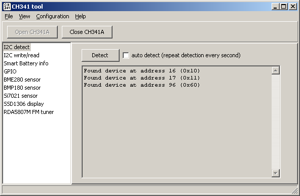
Scanning I2C bus for responding devices, like Linux i2cdetect program. Illustration above shows result with RDA5807M FM radio module connected - this chip has two separate addresses giving access to single and to multiple registers and yet another address (0x60) for compability with TEA5767 chip.
I2C write/read
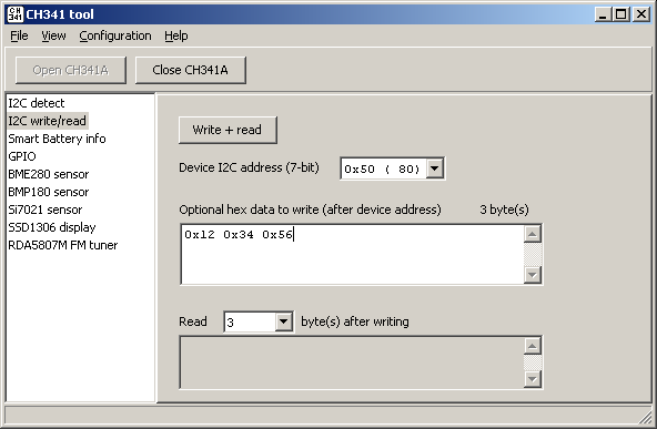
Plain GUI for CH341StreamI2C() API. Sending I2C address, sending optional bytes (from hex string), receving optional bytes (as hex string). Accepts hex string with and without "0x" prefix and with or without comma/whitespace separators.
SPI write/read
SPI on CH341A seems very limited. There are some contradicting informations regarding clock speed, here is my capture from using CH341StreamSPI4() function:

What might be confusing is that clock is irregular - high clock pulses are uniform and have 250 ns, but low state can last around 330 ns (lets call this one regular), around 420 ns (between second and third bit of a byte), around 680 ns (between fourth and fifth bit) or even (between two bytes) around 1170 ns. After averaging this results in ~1.4 MHz clock. CH341A would be not viable for driving WS2812B LEDs.
See anything strange on the picture above? I have not noticed it first as this SPI transmission is decoded correctly by logic analyzer, but it looks like
CH341 is generating short high pulses on MOSI line between clock pulses when sending zeros. These pulses are not from high impedance state,
they are still visible with 1k pull-down added. Definitely not expected. Probably not a problem in most use cases,
but it blocked me from adding HX711 support where I wanted to use MOSI as a clock line.
It is more obvious when sending only zeros:

CS polarity is active low, in my tests CS was activated 11...20 us before the data start and was held down for 930...1110 us after the end of data.
GPIO
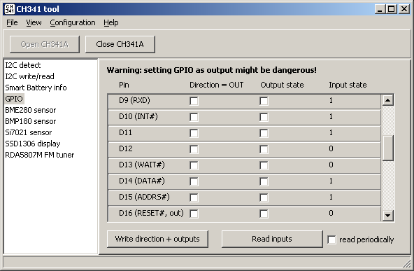
This module has limited practical use - it was used only to test CH341A API. Some mistakes and missing parts in CH341 documentation were found. It could be also useful
for debugging electrical issues.
GPIOs itself are allowing to implement interfaces/protocols that are not natively supported by CH341, they are used by modules for HD44780 display, MDIO, DS1302 and SHT11.
Reading data from sensors
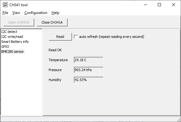
HTU21/SHT21/Si7021 sensors are cheap but from my experience fragile when used outdoors, in particular humidity measurements is prone to returning incorrect data on a rainy days, so it is not only the PCB
but also the sensor itself. I have a small collection of sensors eaten by corrosion and CH341 can be used to double check them.
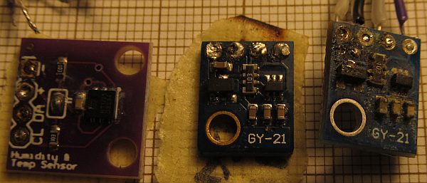
I have ordered BME280 sensor module some time ago with the intention of replacing Si7021, but it was actually the first time I've tested it.
AS5600 magnetic sensor / encoder
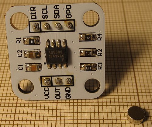
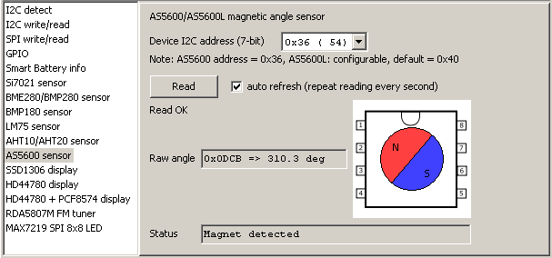
This is a quite interesting magnetic field sensor. It measures absolute direction of magnetic field in one plane, up to 360 degrees with 12-bit resolution, working as an absolute angle sensor. Apart from the I2C data it is able to output voltage ratiometric to Vdd or PWM signal. It looks like a possible replacement for potentiometers used in game controllers like joycon.
The kit I've bought from China comes with a small cylindrical magnet that could be connected to controller/potentiometer axis. This probably helps new users as proper magnetic field orientation and strength is required. Magnet should be placed relatively close to the sensor chip - consider using some isolator to avoid shorts due to sticking to goldpin headers.
HMC5883L magnetometer
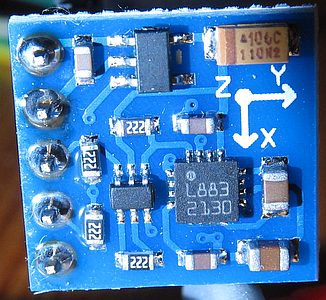
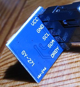
This one is strange. From what I can find, manufacturing of this chip stopped 10 years ago. I2C address matches datasheet (it is not QMC5883L), but mine always returns -4096 (overflow) from Z axis. Is it fake one?
It would be worth checking if header supplied with module is not made of ferrous material (mine was) and swap it for copper one in this case. Note that cheap "Dupont" jumper cables (both headers and wires) are also often ferrous.
It is likely that this sensor would require calibration. The common method is based on collecting tens/hundreds of X/Y data points from different angles (using Earth magnetic field as a reference) and plotting them against each other using spreadsheet. To make it easier I've added functions collecting data (start/stop/reset) when reading it and exporting it to clipboard as CSV text. Steps:
- use "Init" button
- check "Auto refresh"
- position sensor horizontally
- click Calibration/"Start" button
- check "collect data"
- slowly turn around sensor, collecting 100+ data points
- click Calibration/"Copy data to clipboard as CSV"
- import data spreadsheet and create plot from it
Pasting CSV text from clipboard into LibreOffice Calc ("Paste Special") and creating X-Y plot gives chart like this,
showing in this case big offset for X axis:
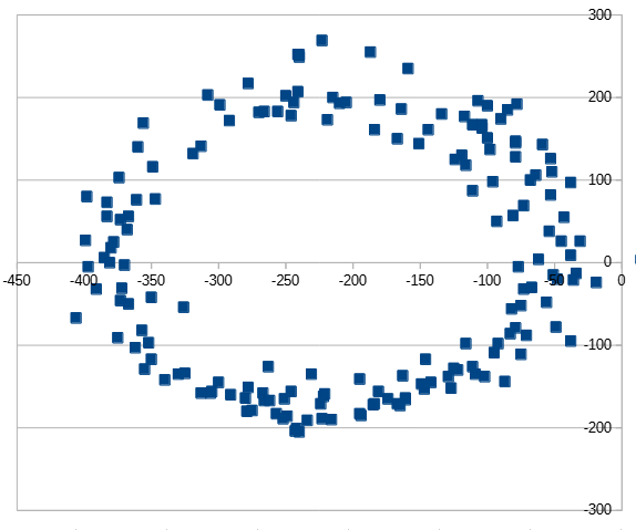
Offset estimation (as half of difference between maximum and minimum induction after rotating sensor in X-Y plane) is also displayed in the tool window and updated with each captured sample. For this particular unit and default configuration this was -212 for X axis and 32 for Y axis. After entering these values into offset edit fields, calculated magnetic angle (between X arrow on the PCB and north) seemed to be matching the real one.
Reading Smart Battery information
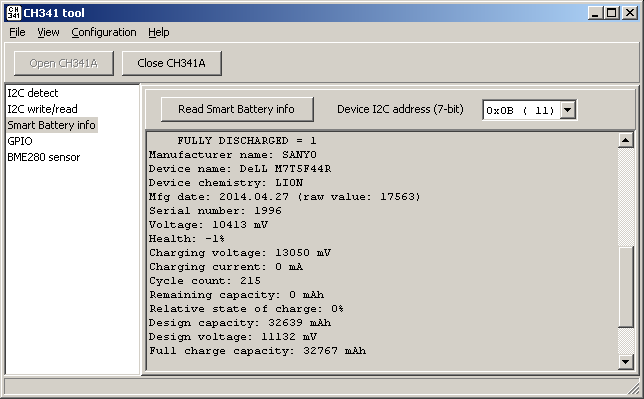
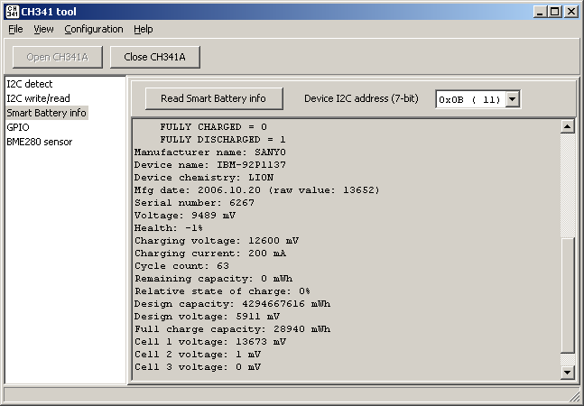
One of the main reasons for writing this tool was the need for diagnosing some old laptop batteries. In the past I was also reselling some batteries bought in bulk and being able to make sure if their controller is fine, read their production date and cycle count would be helpful. I was hoping also for battery repair functionality, it is not trivial though - unlock procedures and/or codes are not publicly known except for few older models like BQ8030.
CH341A is not recommended on NLBA forum as a Smart Battery interface due to poor timings. I have not verified this, but I do indeed have some unstable readings. To gain confidence in data reading needs to be repeated few times.
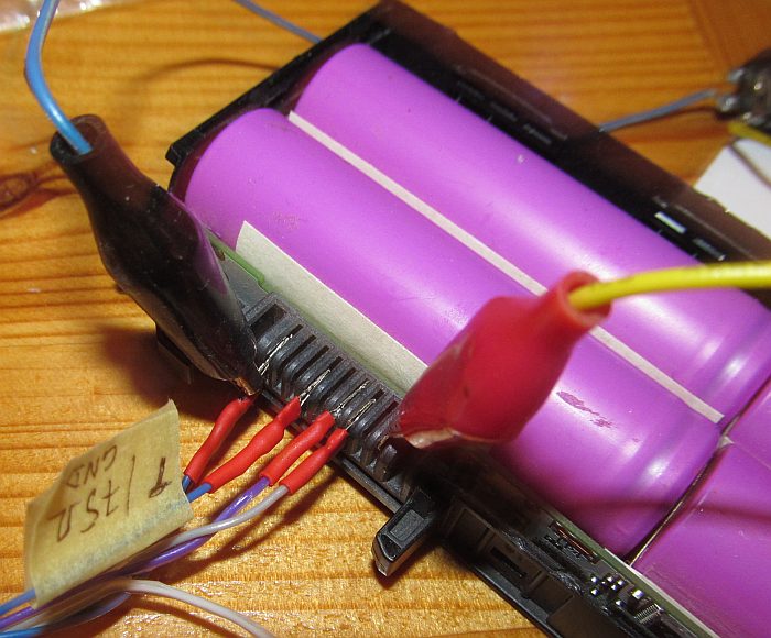
Dell VV0NF battery (based on BQ8050, Sanyo firmware) required +12V power (despite cells being charged) to communicate over SMBus. Pinout: 1 = GND, 4 = T, 6 = DATA, 7 = CLK, 9 = +.
This battery also wasn't working with 100 kHz I2C clock speed, requiring 20 kHz.
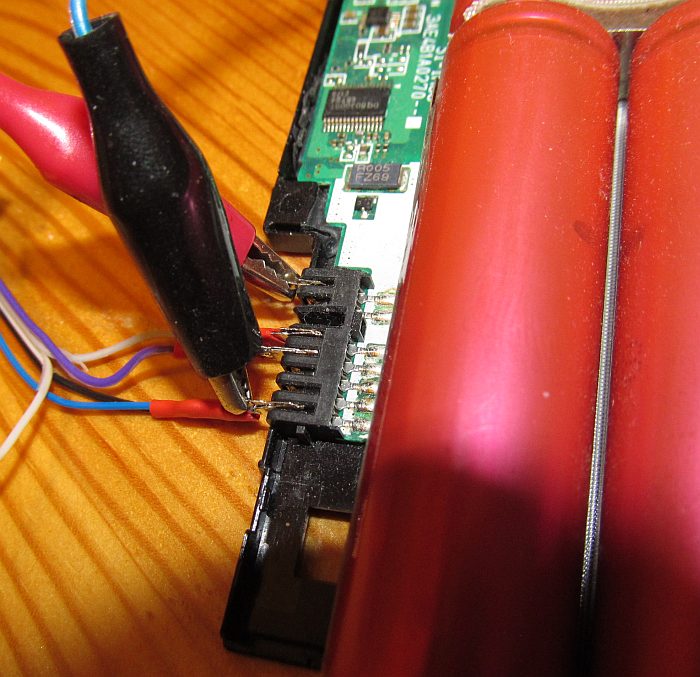
IBM/Lenovo P1137 (for Lenovo R500, T500 laptops, based on BQ8030): plus on the left, GND on the right, DATA on pin 3, CLK on pin 4.
DIP-8 socket can be used as a makeshift cable connector plugged into TEXTOOL socket.
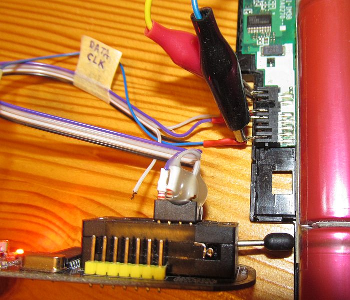
Identifying Smart Battery clock/data can be done by try/error using multimeter and knowing that both these pins would be connected to GND through protection diodes. GND and "+" pins are often marked/visible on the battery and most likely placed on the connector edges.
Note on Smart Battery "T"/System Present pin: it probably needs connecting to GND (I've seen it connected directly or through 1kOhm resistor, I've used 75Ohm resistor myself with Dell VV0NF). If it is not connected I2C on the Smart Battery might be not responding or it might be still active, just reporting battery as locked.
SSD1306 OLED display

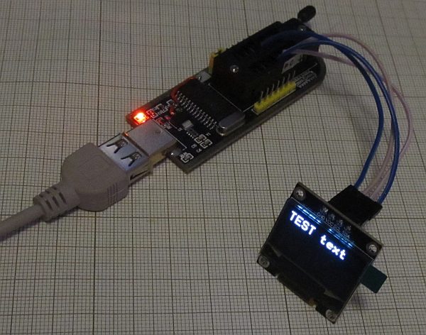
Controlling popular cheap 0.96" OLED display based on SSD1306.
HD44780 display
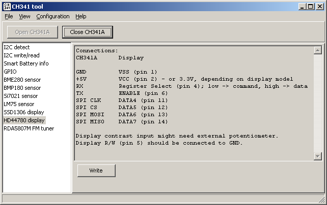
Writing text to HD47780 LCD display connected over GPIO in 4-bit mode. For the connection CH341A programmer pins that are available on goldpin headers were choosen: UART RX/TX and four SPI pins.
HD44780 display connected using PCF8574
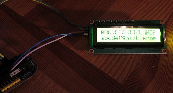
This type of alphanumeric display can be bought cheaply on aliexpress. While HD44780 requires normally at least 6 pins for control, adding PCF8574 (I2C to GPIO expander) allows to use it directly with I2C and up to 8 displays can be controlled with a single interface.
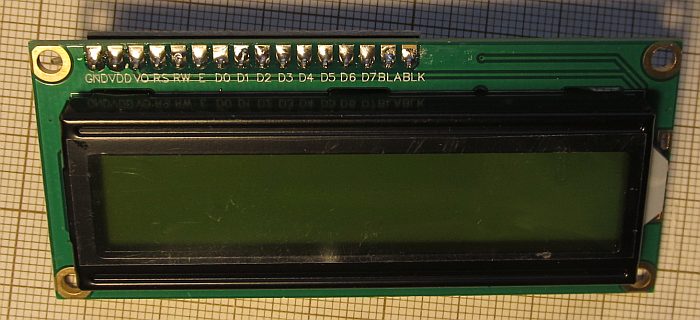
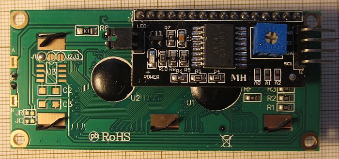
This consists of two boards connected together (sold as a soldered set or separately) - regular LCD display and PCF8574 piggyback.
This particular display requires 5V power supply. I2C/PCF8574 works fine with 3.3V (and 3.3V is fine for I2C even is display is powered from 5V),
but only LED backlight be controlled, LCD itself is blank. There are also variants able to operate at 3.3V, with ICL7660 charge pump soldered as U3 and two extra capacitors.
Note: if the display is blank (either all lit or all black) then contrast might need adjusting (the blue potentiometer).
Connections between PCF8574 and display:
PCF8574  Display
D0       RS
D1       RW
D2       ENABLE
D3       LED control
D4       DATA4
D5       DATA5
D6       DATA6
D7       DATA7
MAX7219 8x8 LED matrix
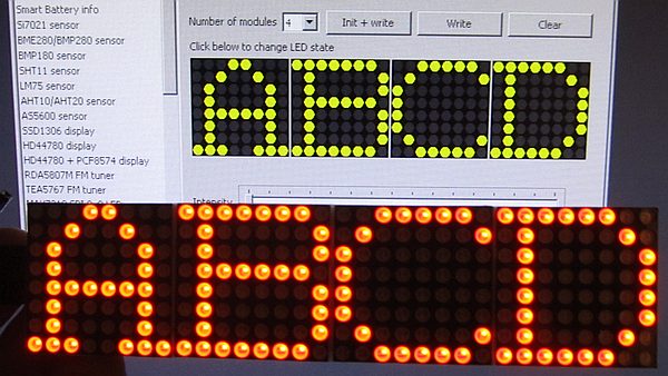
This is an 8x8 LED matrix display controlled by a MAX7219 clone over SPI.
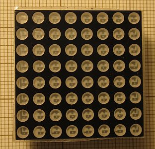
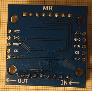
LED matrix is marked as M12088A/B and connected to PCB with two precision SIP sockets. There are few color and brigthness variants, with 25 or 30 mA forward current and 100 mA peak forward current in 1/10 duty cycle, 0.1 ms pulse.
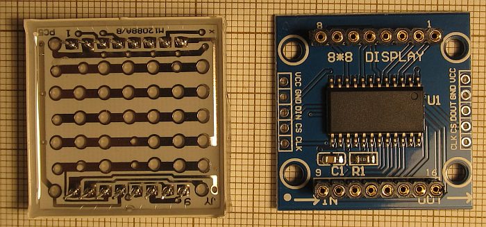
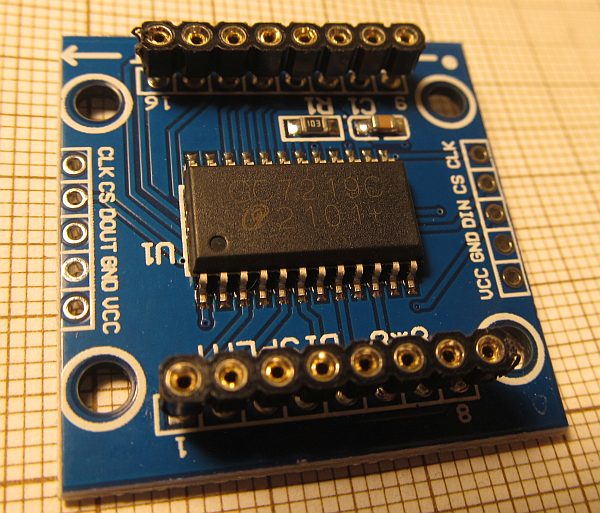
Original MAX7219 would be more expensive on itself than this module. Chip that I found inside is marked as GC7219C.
The GUI part allows to switch state of each LED individually and control display brightness.
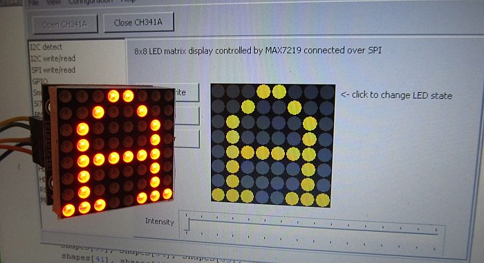
Note: I've used 5V to power this display board, but 3.3V signal voltage levels.
Version 1.5.0 added support for up to 4 8x8 modules in series:
ST7567 LCD display
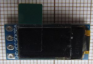
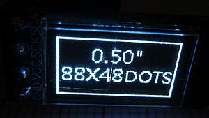
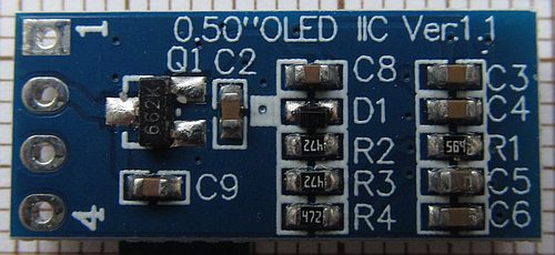
CH1115 OLED display, 0.5", 48x88px
Really tiny OLED with I2C interface. Similar to SSD1306 (same I2C address, mostly the same commands), but not identical - it was not working with previous SSD1306 module.
RDA5807M FM tuner
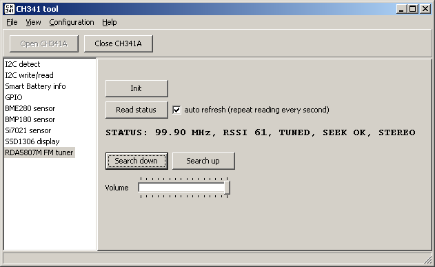
Controlling RDA5807M FM radio tuner. Tuner module can be powered from CH341A programmer. For audio output either active speakers can be used or 32 Ohm headphones can be directly driven.
Si4713 FM transmitter
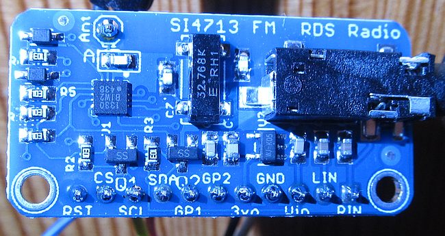
FM transmitter with 76...108 MHz frequency range, stereo encoder and RDS support. Capable of using I2S or analog audio inputs,
but only analog inputs (via mini-jack and header) are connected on popular Adafruit board and its clones (like mine).

Notes:
- connecting RST line (to CH341 TX) is required, without reset device is not detected on I2C
- while Si4713 has AGC and limiter, try to keep audio level in -10...0 dB range (displayed after pressing Read button)
- practical reception range: up to 4 meters without antenna, about 10 meters / 2 floors with antenna wire
- I've observed some problems with RDS reliability (text cut / not displayed fully sometimes), not sure if caused by this transmitter or my receiver
- there is some (little) audible noise when using I2C communication during transmission - perhaps it could be fixed by improving power filtration, otherwise this might be a good reason to keep analog signal amplitude close to maximum and maybe limit I2C status reading if not needed
- my module worked with both 3.3 V and 5 V supply on VIN
Second useful Si4713 function is scanning radio band for noise (signal) level. This is presented in log with dBuV unit and might be used to find unused frequencies.
RDS function can use Winamp 2.x as a text source for artist + title, updating automatically.
Si5351A clock generator
Cheap programmable clock generator with two PLLs.
 CH341A: Si5351A module
The particular module I own is intended to be powered from 3.3V - 5V (there is a voltage regulator and also I2C level converters on the PCB).
It uses 25 MHz reference crystal. Outputs are separated with capacitors.

MDIO
This implements MDIO master functionality, allowing to communicate with a control interface of Ethernet PHYs or switches.
Clause 22 reading/writing window contains bit description for basic and extended PHY registers and shows them as hex/dec/bin values same time.
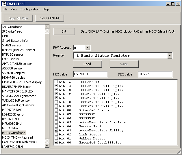
Second MDIO window allows to read/write MMD registers with Clause 22 to Clause 45 access.
Connection (shown also as a note inside application):
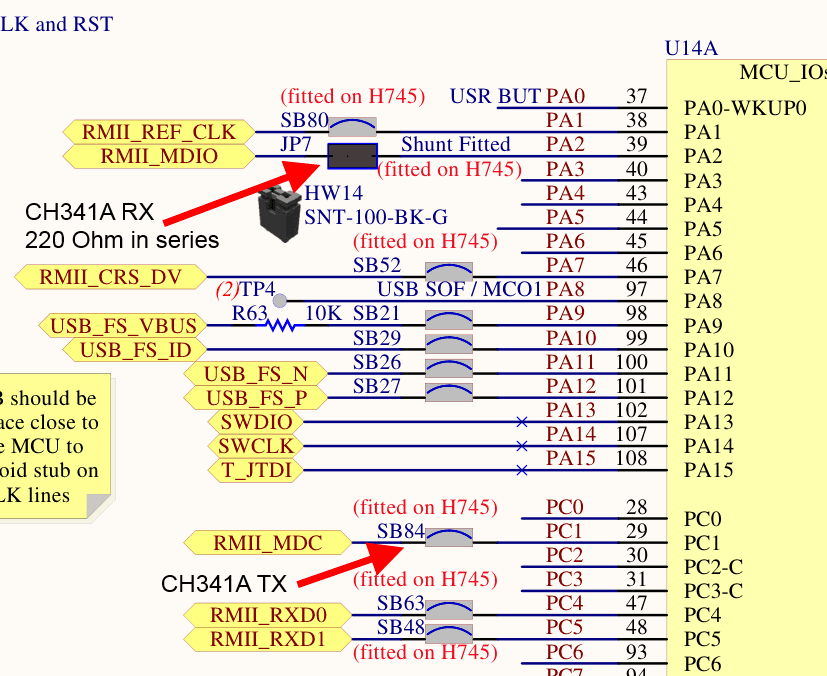
- before version 1.6: using CH341A TX (as MDC) and RX (as MDIO) pins; as CH341A RX line is not open drain output, putting 220 Ohm resistor between RX and MDIO is recommended.
- version 1.6 and up: using CH341 SCL as MDC, SDA as MDIO, should be safe without additional resistors
Ethernet cable diagnostics with LAN8742A
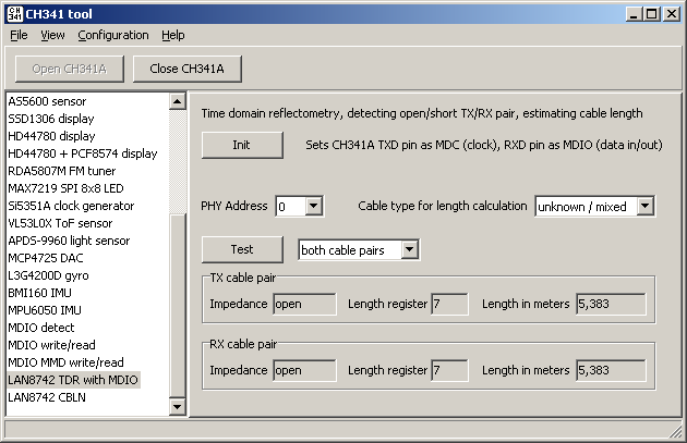
Practical use for MDIO interface: Time Domain Reflectometry with LAN8742A.
When the cable impedance is not matching (no PHY on the other end or damaged cable) LAN8742A is
able to estimate the length of TX and RX Ethernet cable pairs and distinguish between open and short pair.
Note: TDR measurement resolution is somehow low (~0.75 m / bit). Overall measurement error might exceed 10% for unknown cable type (this includes mixed cable types connected together)
according to datasheet but with a known cable type would go down to somewhere in 2-5% range.
If the cable impedance is matching (PHY connected to the other end) and 100 Mbps link is established, cable length can be estimated with LAN8742 CBLN register value. According to datasheet this is limited to up to 120 meters with ~10 m resolution and a hefty error margin of +/- 20 meters.
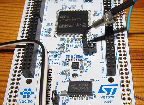
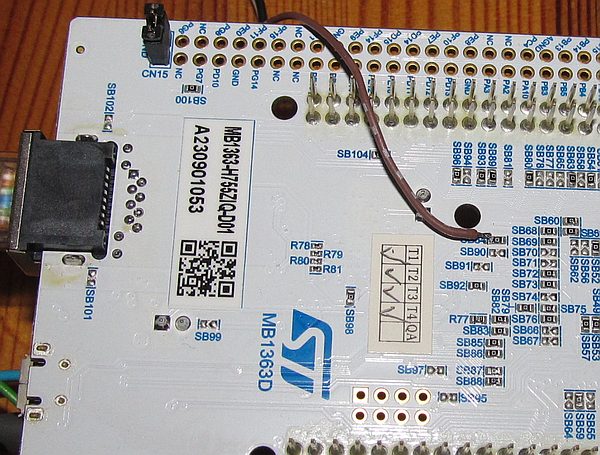
For testing I've used LAN8742A from STM32H755 Nucleo board, erasing STM32 to bring its pins to high impedance state and connecting MDC (= CH341A TX) to SB84 (0 Ohm resistor
on the bottom side) and MDIO (= CH341A RX through 220 Ohm resistor for safety) to JP7 on the top side of the Nucleo board:
CH455 LED and keypad driver
CH455 is a 4-digit LED and keypad driver with I2C interface.
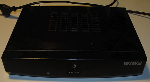
This is WIWA HD102 - one of many DVB-T receivers popular in Poland somewhere between 2014 and 2022, before DVB-T2 was introduced.
While there were many similar receivers, even from the same brand, it had kind of a premium look with larger size and built-in power supply.
Not it is useless this one died actually before DVB-T phase-out because of power supply failure.
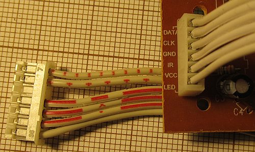
Front panel on the separate PCB uses CH455 to control 4 LED digits and read the state of 3 pushbuttons.


Signals are clearly labeled near the connector.
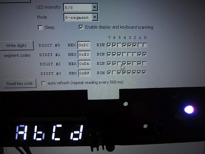
This unit was in use for about 5 years, always on because it was used for TV recording and it had a bug with recording
randomly failing if it was in standby mode.
Time put its toll on the display. On the first digit
from the left (or DIGIT #3 from the controller perspective) segments that belong to the 'C' letter (like 'Channel')
are noticeably darker.
Releases, changelog, source code
- 2023.11.04: version 1.0.0, initial release.
CH341A_tool_1_0_0_bin.zip
CH341A_tool_1_0_0_src.zip
- detecting I2C devices
- writing/reading raw I2C data
- reading Smart Battery information
- writing/reading CH341A GPIO
- reading data from some popular I2C sensors:
- BME280
- BMP180
- Si7021
- writing to SSD1306-based OLED display
- controlling RDA5807M FM radio module
- 2023.11.28: version 1.1.0
CH341A_tool_1_1_0_bin.zip
CH341A_tool_1_1_0_src.zip
- added reading temperature from LM75 I2C sensor
- added writing to HD44780 display using GPIO
- added writing to HD44780 + PCF8574 (I2C) display
- added I2C address selection to BME280
- BMP280 is listed next to BME280
- added AHT10/AHT20 temperature + humidity sensor
- added writing/reading raw SPI data (but CH341 SPI is quite limited)
- added writing to SPI MAX7219 8x8 LED matrix display
- added AS5600 - magnetic rotary position sensor with 12-bit resolution
- 2024.06.29: version 1.2.0
CH341A_tool_1_2_0_bin.zip
CH341A_tool_1_2_0_src.zip
- added Si5351A clock generator support
- added reading distance from VL53L0X laser ToF sensor
- added APDS-9960 light/proximity/gesture sensor reading
- added L3G4200D gyro reading
- 2025.01.25: version 1.3.0
CH341A_tool_1_3_0_bin.zip
CH341A_tool_1_3_0_src.zip
- added MCP4725 DAC
- added BMI160 IMU
- added MPU6050 IMU
- added simple line and square shapes generator (whole screen area test) to SSD1306 test
- MDIO interface, using UART TX (as MDC) and RX (as MDIO) CH341A pins
- device detection (PHY address + ID detection) window
- Clause 22 read/write window with bit descriptions for basic and extended PHY registers
- Clause 22 for clause 45 (MMD) read/write window
- added LAN8742A MDIO TDR (Time Domain Reflectometry) cable diagnostic over MDIO interface
- added LAN8742A MDIO estimated cable length reading for matched cable with 100 Mbps active link
- added option to start each log line with timestamp
- 2025.04.09: version 1.4.0
CH341A_tool_1_4_0_bin.zip
CH341A_tool_1_4_0_src.zip
- added DS1302 RTC (using SDA + SCL + Chip Select, but not I2C protocol)
- added DS1307 RTC
- added Sensirion SHT11 sensor
- added CH455 display and keypad driver
- added ADS1115 ADC
- added options to beep on detection for I2C and MDIO device detection windows
- 2025.06.09: version 1.5.0
CH341A_tool_1_5_0_bin.zip
CH341A_tool_1_5_0_src.zip
- added MAX11601 ADC
- added TEA5767 FM tuner
- added S35390A RTC from ABLIC Inc.
- added DS3231 RTC
- added ST7567 SPI LCD display
- added cascaded MAX7219 4x8x8 LED display
- added HMC5883L magnetometer/compass
- added INA226 power monitor
- I2C device detection window: added option to use i2cdetect-like formatting for output instead of list
- CH341 is reopened automatically if I2C clock speed was changed in settings
- modules can check CH341 I2C clock speed (new discovery: CH341 probably does not support clock stretching, it seems to be added in CH347)
- 2025.11.01: version 1.6.0
CH341A_tool_1_6_0_bin.zip
CH341A_tool_1_6_0_src.zip
- BREAKING: changed pins used for MDIO from TXD + RXD to (safer) SCL + SDA
- I2C detect: added option to limit address range to make oscilloscope triggering easier
- I2C detect: added setting for auto repeat interval time
- added Si4713 FM radio transmitter
- added VEML7700 ambient light sensor
- added CH1115 0.5" OLED display
- added simple timer-based GPIO pattern generator
Note: using CH341A as I2C/SPI/GPIO interface requires "CH341PAR" driver. If you have used CH341A for EEPROM/FLASH programming, you already have it installed. Otherwise you can download it from https://www.wch-ic.com/downloads/CH341PAR_EXE.html or use my local copy: CH341PAR.zip.
It was tested by others with CH341T and should work with other CH341 variants, but their functionality might be limited (CH341T is not supporting SPI and has only some of the pins available).