miniscope v2 - detailed scheme description
This description is based on scheme from 2009.09.23. Currently (2010.04.22) this is the newest one, but keep in mind that scheme may be updated and this page will probably not follow if changes will not be significant.
Digital part
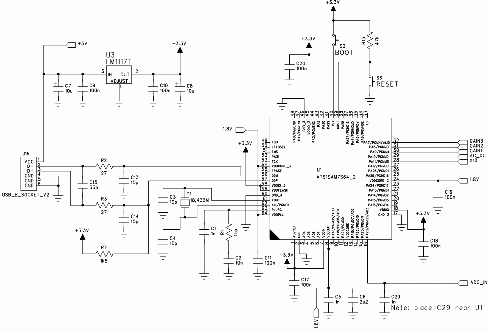
- USB_B_SOCKET
- USB socket type B. You can use type A or mini/micro USB also.
- LM1117T-3.3
- 3.3V voltage regulator. If you have some spare PCB space increasing C8 and C10 or adding additional capacitor for voltage filtering may be recommended. Do not increate C7 too much - you may have a problem with current spike when connecting device to USB port.
- 18.432 MHz crystal
- Frequency is important - USB will not work with other crystal.
- RESET switch
- This switch is probably not necessary. It was supposed to enable to enter booloader (SAM-BA), but unplugging/plugging USB is easier.
- BOOT switch
- Use this to enter bootloader mode. AT91SAM7 device comes with bootloader code in internal ROM. If you want to use bootloader, bootloader code must be copied to internal FLASH memory. To do this you must unplug USB (or use RESET), push BOOT button, plug USB (or release RESET), wait 10 seconds and unplug USB again. At this moment previous FLASH content is overwritten with bootloader, bootloader is loaded and you can use SAM-BA to upload new program. This procedure is quite inconvenient if you are compiling and testing new firmware, but it is reliable and it doesn't require any additional hardware such as JTAG adapter.
- AT91SAM7S64
- This microcontroller has almost everything needed to develop simple oscilloscope: quite fast ADC, 16 kB RAM memory, 64 kB FLASH memory, USB device with PLL generator and some general purpose I/O pins. It's core needs 1.8V supply voltage, but it has internal voltage regulator so only single 3.3V external supply is needed.
- C29 1 nF
- Part of RC anti-aliasing and noise reducing filter.
Analog part
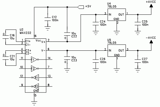
Power supply for analog part uses MAX232 (or similar) as cheap voltage converter. Analog circuits are powered with stabilized + 5V and - 5V voltages.
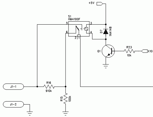
Input attenuator (1:10) allows to measure voltages higher than supply voltages of analog part - it uses electromechanical relay. Input impedance of oscilloscope is about 1 Mohm. You can use any popular npn transistor (i.e. BC237, BC547) to drive relay. Combined with 4066 switches it gives 6 sensitivy ranges.
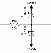
Two Schottky diodes limit voltages to not exceed other analog circuits safe input range. R14 is limiting current flowing through these diodes. R24, D8 and D9 function is similar - they limit ADC input voltage to 0...3.3V range.
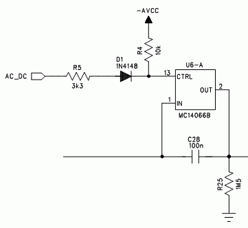
AC/DC switch allows to block DC signal part. 1/4 of 4066 device is used as analog switch.
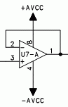
U7-A works as input buffer / voltage follower with high input impedance and low output impedance. In my prototype this is half of TL082 operational amplifier, but many others dual amplifiers will fit too.
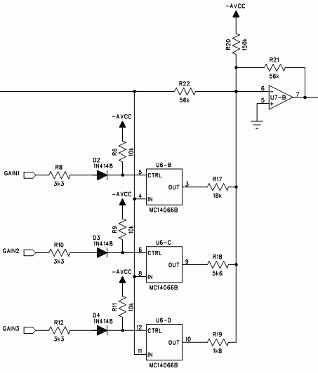
U7-B works as switchable gain amplifier and voltage shifter. In my prototype this is second half of TL082. This is inverting amplifier - device library (armscope.dll/armscope_dma.dll) is compensating this.